Thanks for that, dadod. I've already looked at your verson, and there's no real difference between the two, apart from the LED and single diodes, not sure what you mean about the comp cap. Yet you were getting close to a null DC output, didn't make sense.
Anyway, in the end it came down to the JFETs subcircuit being very sensitive to the source resistors, if you change a single 25R to a 26R say, then your version shows the same symptoms as mine ...
Frank
Why would you increase 4% that resistor, try 1%?
Compensation capacitor is C4 in my schematic, instead C2 in yours.
dado
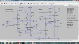
Now I'm really confused about your comp cap, in the opamp.asc I downloaded it's C3 ...
With regard to the resistor, I'm concerned about unstable equilibrium in circuits, when everything looks and works fine if the values are "perfect", but if they vary just a little then the circuit behaves very differently. So, if a DIYer happens to use non-perfect parts, or the active devices are not 100% matched in parameters say, then unwanted, larger scale behaviours can emerge ...
Frank
DIY building pains
YES, I agree! There should be procedure to allow DIYers to MATCH parts. Dale Vishey RN60D, 1% thru hole resistors are readily avaliable. And I believe jfets and bjt's should be matched at the voltage they are gona work in the circuit and not a 9 volt battery. Also most of the parts in my inventory and are avaiable are THRU HOLE (to92) parts. So please don't come up with SOT parts and require a damn microscope to work with them! Just my two cents! Ray
Now I'm really confused about your comp cap, in the opamp.asc I downloaded it's C3 ...
With regard to the resistor, I'm concerned about unstable equilibrium in circuits, when everything looks and works fine if the values are "perfect", but if they vary just a little then the circuit behaves very differently. So, if a DIYer happens to use non-perfect parts, or the active devices are not 100% matched in parameters say, then unwanted, larger scale behaviours can emerge ...
Frank
Sorry, the part of zip file was Wurcer shunt compensation(C3), look at the figure at the post http://www.diyaudio.com/forums/anal...screte-opamp-open-design-145.html#post3187792 C4 connected between collectors of the Q8 Q9 and R1 R2.
dado
A comment from the sideline to Dadod.
When comparing circuits, it is important to make it fair.
If I interpret your circuit properly you are using Ccomp = 100p in Scott's circuit, while using 22p in your circuit, it is of course true that you can lessen Cc when you take it back to the input stage instead of gnd, but not as much as you do.
Here is a Loopgain comparison and a transient THD comparison, each with gain = 5
Another thing is that you use 1kohm load instead of 600 ohms and very low values in FB network.
Cheers
Stein
Attachments
-
AC Analysis Dado Cc 22p.pdf46.8 KB · Views: 81
-
Transient Analysis SW Cc 100p.pdf33.3 KB · Views: 65
-
Transient Analysis SW Cc 44p.pdf33.3 KB · Views: 63
-
Transient Analysis Dado Cc 44p.pdf33.3 KB · Views: 55
-
Transient Analysis Dado Cc 22p.pdf33.3 KB · Views: 55
-
AC Analysis SW Cc 100p.pdf47.2 KB · Views: 66
-
AC Analysis SW Cc 44p.pdf46.7 KB · Views: 57
-
AC Analysis Dado Cc 44p.pdf47 KB · Views: 56
You guys are moving fast, I would hope some kind of breadboard could be made before anyone spends time or money on parts and boards. The last one worked perfectly according to sim but no need to push our luck.
Less time for this for a few days.
EUVL - Thanks for the cascode devices I missed those (J310 which I frequently use for this is only 25V). Boards would be fine but we need a definitive schematic which will still take a while.
On the load drive, this would require a high current buffer or hefty output devices (another version). I never intended this to do 50 or 30 Ohms by itself.
Ready when you are.
You still have my email address ?
Patrick
Yes
A comment from the sideline to Dadod.
When comparing circuits, it is important to make it fair.
If I interpret your circuit properly you are using Ccomp = 100p in Scott's circuit, while using 22p in your circuit, it is of course true that you can lessen Cc when you take it back to the input stage instead of gnd, but not as much as you do.
Here is a Loopgain comparison and a transient THD comparison, each with gain = 5
Another thing is that you use 1kohm load instead of 600 ohms and very low values in FB network.
Cheers
Stein
My intension was not to compare, just simulate it. First I don't know what are suggested JFETs and BJTs. I've got couple of 2sk389 and 2sj109 and I need good line preamp so I simulated it according to that. Regarding GNFB Scott did not suggested starting values, so I used very low values as it gives better response.
You are right about Cc, half than the shunt value is better(47pF) and still distortion is lower.
I noticed that the opamp distortion is quite sensitive to the source impedance.
Here, this one is with more powerful output transistors, maybe Scott can suggest correct currents for it?
dado
Attachments
> I wanna see pcb's when i get back...
..........
Will take quite a few days, since I do not use PCB layout software.
They cannot do what I want to do; to many restrictions.
Patrick
It depends on what's on your mind. Many tricks can be done with modern PCB software, it just takes some learning time.
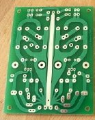
Here's one 10 years old example from my past. All lines drawn by hand within that particular software enviroment
")
Attachments
If I want to draw every line manually I have better software to use than PCB software.
I am not restricted to any grid or standard device pin layouts.
Of course you are welcome to take over. I am sure Scott will welcomne that.
And I certainly have more than enough on my to-do list waiting to get done.
Patrick
I am not restricted to any grid or standard device pin layouts.
Of course you are welcome to take over. I am sure Scott will welcomne that.
And I certainly have more than enough on my to-do list waiting to get done.
Patrick
For the F5X project, fitzfish tried over a period of months (< 100hrs.) to duplicate a PCB layout that I did with a mechanical CAD software.
The only reason then was that I had no means to convert a dwg file to Gerber.
Even with his huge effort, which I found out only afterwards, he still could not replicate all the features that I had in the original.
This is especially so with the shaping freedom that I had with dwg files.
So while at one stage I was motivated to learn PCB software, in the end I decided not to. For exactly those reasons.
And of course in the meantime, the conversion problem from dwg to Gerber is solved.
Of course there are applications, like complicated circuits, where PCB layout software will be useful to avoid mistakes.
But for simple analogue layouts I am sticking to dwg.
Anyone who is skilled in Eagle or whatever else who wants to take on the challenge can contact me.
But you might want to check with fitzfish first to verify what I just said.
And he is, as I know, very experienced with PCB work.
So you can figure out why he needed 100hrs.+ for the simple F5X PCB.
Patrick
Eagle allows you to create any arbitrary copper polygon shape and name its net, so it maintains connectivity, etc., while allowing the flexibility of hand-drawn arbitrary shapes. However, it takes a bit of effort to use it effectively for anything other than ground and power planes.
Im a mechanical engineer in the ground and have worked alot with Autocad and inventor, I have also worked a bit with orcad capture and orcad Layout. But I can not see any direct advantages to do the cad part in Autocad instead of Orcad layout?
And misunderstand me correct, I mostly hate orcad Layout but I think it is very beneficial to have the schema in capture and select a component there and the same component light up in the layout program and vice versa.
And misunderstand me correct, I mostly hate orcad Layout but I think it is very beneficial to have the schema in capture and select a component there and the same component light up in the layout program and vice versa.
I'm keen to know what people have found effective, as I may soon break down and start doing layouts. Much as I appreciate the efforts of those I've done business with over the years, the only person so far I've worked with who has good instincts about routing is way too busy in a company of his own. With others they either know too much and second-guess, or always make at least one error, or make a plurality of errors, or have depressing attitudes.
So anyone wants to take on the challenge to redo the layout in post #1379 using a PCB layout software ?
Schematics is here :
http://www.diyaudio.com/forums/anal...discrete-opamp-open-design-3.html#post3138073
Footprint is 10x10mm, DIP8 single opamp pin out for Pins 2,3,4,6,7.
Components all on the top side for heat sinking.
Bottom side space reserved for DC trim resistors and frequency compensation network.
Patrick
For my personal use, I would like to see a layout to is pin compatible with a JE990 opamp. I don't use any 8 pin DIP opamps except to drive meters and in power supplies. But my recording console is full of JE990s. Just my 5 cents. I may have to lay one out for myself. Ray
- Home
- Source & Line
- Analog Line Level
- Discrete Opamp Open Design