Brad,
Yes, same die as the 2SK209 single in sot 23 also.
The 2SK880 single in a SC-70 (100mw max pdis) is also the same die... which is available from Mouser in BL.")
Dave
...of the Toshiba dual N device, the 2SK2145, which is apparently a two-chip dual using 2SK117 devices
Yes, same die as the 2SK209 single in sot 23 also.
The 2SK880 single in a SC-70 (100mw max pdis) is also the same die... which is available from Mouser in BL.
Dave
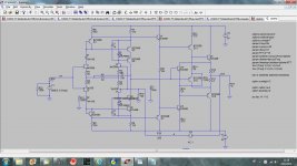
This is my simulation with no transistor selection, just took it from LTspice librery, exept jfets.
I moved the compensation cap and distortion halved.
dado
Can't see the lines on the schematic.
> They sent samples of all grades and more than one lot was represented, so it looks like there is progress.
Didn't they give samples away at one of the Audio meetings (Burning Amp) in the US a year or two ago ?
If there were samples then what kept them from volume production, one hesistates to ask ?
Patrick
Didn't they give samples away at one of the Audio meetings (Burning Amp) in the US a year or two ago ?
If there were samples then what kept them from volume production, one hesistates to ask ?
Patrick
> They sent samples of all grades and more than one lot was represented, so it looks like there is progress.
Didn't they give samples away at one of the Audio meetings (Burning Amp) in the US a year or two ago ?
If there were samples then what kept them from volume production, one hesistates to ask ?
Patrick
Yes, I got no answer. All samples until this batch had the same date codes and I worry that they need to sell at least more than we buy to make it worthwhile.
MicroCap10 simulation
Scott,
I entered your design into Microcap 10 Pro. Used 20 dB gain (2k21 and 221R). Exchanged some of the BJTs into 2SA1360/SC3423, and changed some values to get the currents I wanted to have. Used one of the 250R resistors to null DC offset.
OL gain is ~100 dB and F-3dB = 330 Hz.
THD20k into 600 ohms and at 3Vrms output voltage = 0,0006%.
SNR is 107 dB rel. 1Vrms, 20-20kHz, flat.
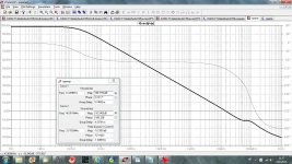
I have attached some nice THD vs Freq, THD vs Vout, THD+noise vs Vout sweeps.
BTW, what does R22 (50R) in your schematic do?
/S
Scott,
I entered your design into Microcap 10 Pro. Used 20 dB gain (2k21 and 221R). Exchanged some of the BJTs into 2SA1360/SC3423, and changed some values to get the currents I wanted to have. Used one of the 250R resistors to null DC offset.
OL gain is ~100 dB and F-3dB = 330 Hz.
THD20k into 600 ohms and at 3Vrms output voltage = 0,0006%.
SNR is 107 dB rel. 1Vrms, 20-20kHz, flat.
I have attached some nice THD vs Freq, THD vs Vout, THD+noise vs Vout sweeps.
BTW, what does R22 (50R) in your schematic do?
/S
One last one for today, the fully complimentary version. If SK170/SJ74 FET's are used high source impedances are not recommended.
Attachments
Can't see the lines on the schematic.
Better?
Attachments
I cascode 2SK170 with J111 and 2SJ74 with J174.
Works quite well. But still only 30V.
To go higher one needs to use BJT or MOSFET cascode, I am afraid.
Makes things too complicated.
Patrick
The J111 looks good here. This is a problem, un-cascoded the distortion is degraded a bit with even a 10k source. Not that big a deal, I am measureing at extremes 20V at 20k. At normal line levels the effect is small. Will need a little more work.
Dick, did you measure yours with a 50k volume control?
Better?
That's better, interesting. I think you are missing a couple of diodes on the right side of the input stage, this might saturate the cascode.
That's better, interesting. I think you are missing a couple of diodes on the right side of the input stage, this might saturate the cascode.
I used LED instead, that is 1.9 V, more then two diodes.
Would you be kindly enough to post your LT Spice files ?
Then we can all play with it.
Many thanks in advance,
Patrick
If you meant me here it is.
Attachments
I compliment those who use "complement".
ha, sorry for the laziness, autocomplete gives me that as I use it more often I guess and I havent trained myself to correct it. it also isnt set in my brain to use complement as a singular noun (by itself), or complementary as a noun at all… I know its correct, it just isnt habit. it seems to get used as a technical adjective, noun, or pronoun interchangeably.
Last edited:
pronoun? lol..noanyway back on topic, I can see another model of custom jfet SMD heatsink coming on. I guess I better break out the matching rig and go through my j103/k246. would these compound mosfet networks be of any use here? i've been thinking about getting some to play with for a while.
fairly low voltage though
Last edited:
Don't the CCSs, J1 & J2 isolate Q6, 7, 8, 9, 11, 35 and hence Q15 from the signal path?... Re: post #1380 circuit ..
Q15 just samples a voltage to drive the current sources for the output stage, this saves some devices and keeps all currents set by the input stage. It also provides a slew boost to the output devices, not much benefit here at band limited audio but it makes prettier square wave pictures
Sorry about the bad JPEG conversion that dropped some 1 pixel wide lines, post #1387 has a schematic that caught this.
I can see a signal path through Q15 on some of the later 'symmetrical' versions but not on the simple
eek #1380 circuit.Or are there some missing tracks on #1380
ricardo
Excuse, my ignorance but az i kunt reed en rite, I'm only on page 97 in my journey through these guru postings.
I get the impression this is a competition to be judged against Guru Wurcer's offering via LTSpice
From his #1380 post, the constraints are
- -100dB for 2nd, 3rd etc @ 20kHz with 20dB gain into 600R
- 2nV/rtHz noise
- zillion V/us into 10n
- 50R headphones too.
Please correct me if I'm wrong. I'd like to enter with my offering using NOS Mullard EF37As.
- Home
- Source & Line
- Analog Line Level
- Discrete Opamp Open Design