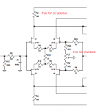
What about this dirty trick (see 1st attachment) to trim AC symmetry and lower output THD _without_ affecting DC balance? Without it THD is about 0.00065% from 100 Hz up to 20 kHz @ 0 dBV into 30 ohm load (almost only 2nd, measured with a subtractive method); with the shown trick, provided the trimmer is a good quality 10-turns one, you can lower 2nd harmonic down to an impressive -130 dBV, while 3rd stably sits at about -125 dBV (@ 1 kHz, 0 dBV into 30 ohm), which means something like < 0.0001% THD (rising at ~ 0.0002-0.0003% @ 20 kHz) - it seems THD doesn't vary at all with time (on a couple of hours scale, at least). I must admit that lowering further and already quite low THD figure could be a mere technical exercise, nevertheless getting down to < 0.0001% @ 30 mW into 30 ohm using 10 devices isn't actually an everyday experience ")
L.
L.
Attachments
I may start a new thread for in-depth explorations of linuxguru's approach.
Thumbs up! I'm really interested
L.
Thumbs up! I'm really interested
L.
I also just got word (thanks D!) that there is some prior art closely resembling the approach, if not subsuming it. I am looking at the claims soon --- not that any of us in here should be deterred from diy applications
From the descriptions it would appear as if the basic notion of the current sensing for compensation is part of a couple of patents.
Sorry to go a bit OT again, but just to extend: I agree that there are distortion mechanisms at work creating audible problems, that can certainly be classified as "exotic", as in that they are imposing themselves from outside of the world of the direct and generally accepted parasitic behaviours of the circuit parts. And these other mechanisms either interfere with the "textbook" functioning of the feedback, or lie beyond the area of the circuit that the FB looks at.I don't think so, fas42. Reducing feedback also reduces potential distortions that are MORE exotic than we can easily measure.
So, IMO, playing with the level of FB is not addressing the real problems of getting correct sound, I'm with Bruno in saying there ain't no such animal as too much, correctly functioning, feedback. Firstly, make sure that the area of the audio system that has designed in FB as part of its structure is working as "perfectly" as it can, and secondly address the problems that lie elsewhere ...
There's a simple issue at the heart of audio: test after test says that people begin to lose the ability to hear "distortion" at about 60dB down, at -80 it's completely invisible; and I agree with these findings -- yet people thrash around, fighting to get, and achieving -120dB performances, in parts and circuits, which other people then dismiss as having obvious, audible characteristics. So what's going on ... ??
Frank
There's a simple issue at the heart of audio: test after test says that people begin to lose the ability to hear "distortion" at about 60dB down, at -80 it's completely invisible; and I agree with these findings -- yet people thrash around, fighting to get, and achieving -120dB performances, in parts and circuits, which other people then dismiss as having obvious, audible characteristics. So what's going on ... ??
One of the things I think is going on is there's almost an obsession with single tone THD measurements which tends to exclude other more promising avenues of measurement. Where are the multitone IMD measurements which Audio Precision made possible decades ago?
The reason single-tone testing doesn't cut it is its crest factor is very unlike music. Music (not including the modern highly compressed genres as 'music' here
) spends most of its time below -20dBFS whereas a full-scale sinewave spends half its time above -6dBFS. Hence traditional THD doesn't weight a circuit's linearity where it matters most - around the zero crossing.abraxalito,
So what are you proposing as a new test? Do we chose a three tone sample with 20hz, 1khz and 20khz and test with burst waveforms simultaneously, or do a longer time frame test reaching the upper power limits of the device in question? In speaker testing we use log chirp testing to see what is going on and perhaps something like that would work for an amplifier at the correct levels to work the NFB circuits to see what is happening? Give us an idea what would be a better test than single frequency testing methods.
So what are you proposing as a new test? Do we chose a three tone sample with 20hz, 1khz and 20khz and test with burst waveforms simultaneously, or do a longer time frame test reaching the upper power limits of the device in question? In speaker testing we use log chirp testing to see what is going on and perhaps something like that would work for an amplifier at the correct levels to work the NFB circuits to see what is happening? Give us an idea what would be a better test than single frequency testing methods.
The sound of 20,000 tones -
The harmonics of a single tone produces some 'grass' on the FFT plot. Say .01% thd worth; Can't be heard. More simultanious tones, more grass growning and IM grass, too. After 20,000 tones have been applied, that .01% THD of each of thousands of tones adds up to enough to reach audible levels. The audible effect is an equivalent increase in the background noise level. Which is described as masking details or changing character of the sound depending on music freq content played. This might be why we need Really low thd numbers on a single tone test.... to prevent the accumulated harmonics of many simultaneous tones from reaching an audible threshold. -Thx RNM
The harmonics of a single tone produces some 'grass' on the FFT plot. Say .01% thd worth; Can't be heard. More simultanious tones, more grass growning and IM grass, too. After 20,000 tones have been applied, that .01% THD of each of thousands of tones adds up to enough to reach audible levels. The audible effect is an equivalent increase in the background noise level. Which is described as masking details or changing character of the sound depending on music freq content played. This might be why we need Really low thd numbers on a single tone test.... to prevent the accumulated harmonics of many simultaneous tones from reaching an audible threshold. -Thx RNM
Last edited:
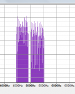
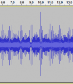
Three tones would certainly be a step in the right direction, but why stop there? Here's a test signal I composed recently but haven't tried out on any real circuits yet as I'm not done playing with it. I plan to add some LF components - this signal has just over 100 discrete tones about -40dBFS each. The second image shows the time domain - the crest factor is quite unlike a sine and I've not done the 'Schroeder Phase' thing to minimize it
Attachments
After 20,000 tones have been applied, that .01% THD of each of thousands of tones adds up to enough to reach audible levels.
Does this account for masking (i.e., audibility in the presence of 20,000 large signals)? And how do you fit 20,000 different tones into the audible bandwidth and still be able to see any harmonics? Any references on this?
Of course it does - my point was that the AP made it more accessible to the average punter. Just as computers went back prior to the founding of Microsoft yet it was Bill Gates who made them widely accessible.
Gee, I had a Heathkit IM analyzer when I was a young lad back in the '60s. Lots of them were around (also Eico, Knight). A hell of a lot more accessible to THIS average punter than a $10k AP. Now, I'd certainly rather have the AP, it does a lot more and does it better, but the price is well out of the range of any non-rich non-professional.
Gee, I had a Heathkit IM analyzer when I was a young lad back in the '60s. Lots of them were around (also Eico, Knight).
How did that allow you to create your own multitone test waveforms?
Charting new territoty here -- See #1052 for yet another way to do it besides using AP equipment.Does this account for masking (i.e., audibility in the presence of 20,000 large signals)? And how do you fit 20,000 different tones into the audible bandwidth and still be able to see any harmonics? Any references on this?
It isnt a masking test. But the affect has been discribed and it seems to corrallate with this total tones harmonics higher number's affect.
Do the rt1/2 sum of the sq of all the harmonic levels and tell me what it comes out to be with 20K tones each with harmonic of .01% Any approach you choose will give a large total distortion number. Or even 1000 tones and thier harmonics at .01% each (say 2,3, 4 and 5th only). Would it be audible if the detection threshold is .05% or less? Should be. -RNM
Last edited:
Wait a minute ... is that a valid way of looking at how a circuit "adds" further distortion when the signal is more complex? As far as the circuit and the parts within are concerned, all they ever see is an input wiggle, a varying voltage signal, they don't "know" that they're supposed to break everything down into sine waves, amplify each individually with at attendant measure of distortion, and then add it all up in a nice, mathematical way. Of course, if they do, hats off to such smart componentry!!Do the rt1/2 sum of the sq of all the harmonic levels and tell me what it comes out to be with 20K tones each with harmonic of .01% Any approach you choose will give a large total distortion number. Or even 1000 tones and thier harmonics at .01% each (say 2,3, 4 and 5th only). Would it be audible if the detection threshold is .05% or less? Should be. -RNM
At any point in time the output signal will be a certain value incorrect, the instantaneous distortion component so to speak. And to me that will never vary substantially from what the circuit state would be if it happened to be amplifying a pure sine wave with the waveform exactly corresponding to a part of that curve. That is, unless you want to take a lot of "memory" and similar effects into account ...
Frank
A somewhat related idea would be the "Noise Power Ratio (NPR)" test used to evaluate the FDM telephony systems from about the 1940's through the 80's.Or -- A random wide frequency band (flat) noise generator as source used with a high precision subtractive circuit to get I/O difference level. -RNM
The idea was to apply a random, broadband signal (band-limited noise) to the whole information bandwidth of the system. Then a very sharp, narrow, notch filter removed the noise from a small segment of the input spectrum (roughly 1% or less of the total information bandwidth). As that clean notch in the input spectrum passed through the system it would collect corruption, crud, and grunge from a wide range of sources - basic thermal noise; THD products from spectral components at lower frequencies; IMD products from spectral components at a variety of frequencies; power-supply ripple modulation of spectral components near the notch frequency; etc.
At the system output, an equally sharp, very narrow band, bandpass filter would measure the power in the notch. Comparing this to the power of the broadband input signal gave the "Noise Power Ratio". Usually there were three measurement notches - one at the lower end of the system passband, one at midband, and one in the upper end. This was primarily an evaluation test to gauge how good a system was overall, not an analytical test to localize a problem. (Sort of like a physician using temperature, pulse, and blood pressure to evaluate your general health - by themselves, those 3 measures don't diagnose any particular illness.)
While this technique was developed for use in FDM telephony systems where the information bandwidth extended from about 50 KHz to several MHz (a frequency ratio around 100:1), I suspect the principles could be applied to an audio bandwidth of 20 Hz - 20 KHz (1000:1 ratio). As with the FDM test sets, the challenge would be to create the notch and bandpass filters. Forty years ago they did it with passive analog filters; today it may require a combination of analog and digital filtering.
More information:
"Noise Power Ratio (NPR)" (Walt Kester) at < http://www.analog.com/static/imported-files/tutorials/MT-005.pdf >
"Noise Power Ratio Measurement Tutorial" (Allen Katz and Robert Gray) at < http://lintech.com/PDF/npr_wp.pdf >
Thirty years ago the common reference book for NPR testing was published by Marconi Instruments and called (as I recall) "The White Noise Handbook", but it's probably long out of print.
Dale
Wait a minute ... is that a valid way of looking at how a circuit "adds" further distortion when the signal is more complex? As far as the circuit and the parts within are concerned, all they ever see is an input wiggle, a varying voltage signal, they don't "know" that they're supposed to break everything down into sine waves, amplify each individually with at attendant measure of distortion, and then add it all up in a nice, mathematical way. Of course, if they do, hats off to such smart componentry!!
At any point in time the output signal will be a certain value incorrect, the instantaneous distortion component so to speak. And to me that will never vary substantially from what the circuit state would be if it happened to be amplifying a pure sine wave with the waveform exactly corresponding to a part of that curve. That is, unless you want to take a lot of "memory" and similar effects into account ...
Frank
Its as valid as a single tone or two tones or three tones or multiple tones (AP) we use now... just more tones. Its a way to gauge the total level of all the harmonics generated... similar to when music frequencies are the input being worked upon.
A somewhat related idea would be the "Noise Power Ratio (NPR)" test used to evaluate the FDM telephony systems from about the 1940's through the 80's.
The idea was to apply a random, broadband signal (band-limited noise) to the whole information bandwidth of the system. Then a very sharp, narrow, notch filter removed the noise from a small segment of the input spectrum (roughly 1% or less of the total information bandwidth). As that clean notch in the input spectrum passed through the system it would collect corruption, crud, and grunge from a wide range of sources - basic thermal noise; THD products from spectral components at lower frequencies; IMD products from spectral components at a variety of frequencies; power-supply ripple modulation of spectral components near the notch frequency; etc.
Dale
This or something like it that gets at the total noise/harmonics of a system rather than a single tone's harmonics would be more realistic of what we are being exposed to when using the audio gear for listening to music signals. Thx for the idea. -RNM
Last edited:
- Home
- Source & Line
- Analog Line Level
- Discrete Opamp Open Design