Well John, notice the filename. I just sucked that up, years ago onto my disk, when I saw it, sometime-somewhere? You appear to confirm it's close enough? I should take the "maybe" off the filename?Fig, Why did you post the Vendetta Schematic? Just for 'completeness' ? It won't work as a headphone amp very well.
Anyway, I'm thinking this is a discrete "OpAmp" thread, not a head Amp thread. Although, there are those looking to drive 30 ohms...
I beleive the SCP-2 is very similar to an idea you presented in post #179 some thime back, with the addition of a buffer of coarse. I should have raised my question then. But this thread moves so fast some day's I can't keep up and work too. That's O.K. though, this is one of the best threads going right now for some of us. Thanks BTW! I'm sure there is much more interest than your reading.

Nice circuit
Would you describe your thinking about your original circuit -- the C-CB? Thx - Richard
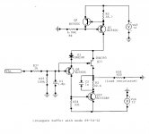
Here's a novel buffer with just 4 actives including a current source. It simulates with THD20 of -95 dB at 2V amplitude into 600R, at a quiescent current of 12 mA.
This topology differs from one published in these forums a few years ago. I hereby exercise my right to name it: Cantilevered-Cascode Buffer. I hereby also exercise my right to place it in the public domain, free of patent encumbrances. No warranty, express or implied, is provided.
Would you describe your thinking about your original circuit -- the C-CB? Thx - Richard
Last edited:
Would you describe your thinking about your original circuit -- the C-CB?
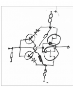
The aim is to keep the lower JFET (in the signal path) operating at close to constant Id, as well as constant Vdg. This will ensure that Vgs does not vary much. By adjusting the current source (upper JFET) to close to Idss for the lower JFET, Vgs can also be brought close to 0. Almost all of the load current swing occurs in the NPN, where the Vbe variation is not directly in the signal path, thus eliminating Vbe compressive distortion.
cantilevered redux
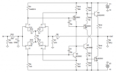
Here is a version with a bit more voltage across the input JFET, a bit more current to operate it closer to Idss and improve load swing somewhat. The upper JFET has been replaced with a ring-of-two current source which raises output resistance, particularly at the higher positive input voltages, at the cost of one more bipolar. The ambient temp stability of the output offset will likely be a bit worse.
R2 minimizes thermal shifts due to dissipation changes in Q10. R34 is adjusted for about minimum distortion at 1kHz and 4V p-p out. C1 flattens the high frequency response. The peaking-free response is -3dBr at 62MHz. The voltage gain is slightly less than unity primarily due to the input voltage divider effect.
Sims predict distortion to 20th at 1kHz and 4V p-p out of -124.6dBr, dominated by third (it looks like 2nd could be further reduced). Near the onset of clipping, at 18V p-p out things have degraded to -92.3dBr, still an excellent result.
Sorry for the untidy out-of-sequence ref designators.
The aim is to keep the lower JFET (in the signal path) operating at close to constant Id, as well as constant Vdg. This will ensure that Vgs does not vary much. By adjusting the current source (upper JFET) to close to Idss for the lower JFET, Vgs can also be brought close to 0. Almost all of the load current swing occurs in the NPN, where the Vbe variation is not directly in the signal path, thus eliminating Vbe compressive distortion.
Here is a version with a bit more voltage across the input JFET, a bit more current to operate it closer to Idss and improve load swing somewhat. The upper JFET has been replaced with a ring-of-two current source which raises output resistance, particularly at the higher positive input voltages, at the cost of one more bipolar. The ambient temp stability of the output offset will likely be a bit worse.
R2 minimizes thermal shifts due to dissipation changes in Q10. R34 is adjusted for about minimum distortion at 1kHz and 4V p-p out. C1 flattens the high frequency response. The peaking-free response is -3dBr at 62MHz. The voltage gain is slightly less than unity primarily due to the input voltage divider effect.
Sims predict distortion to 20th at 1kHz and 4V p-p out of -124.6dBr, dominated by third (it looks like 2nd could be further reduced). Near the onset of clipping, at 18V p-p out things have degraded to -92.3dBr, still an excellent result.
Sorry for the untidy out-of-sequence ref designators.
Attachments
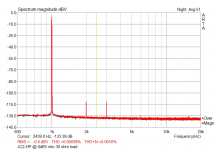
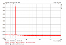
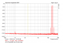
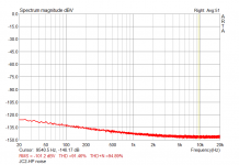
Some more info on the circuit I did breadboard yesterday: schematics (R1 is actually supposed to be trimmable to zero output offset), THD @ 0dBV & -5dBV, 1 kHz into 30 ohm, IMD, output noise with input shorted. THD seems to drop quite a bit after a few minutes of warm up, although at such a low THD level I'm really pushing the limits of my EMU - have to try a subtractive method, or a notch. OLG is about 73 dB midband (1 kHz), and still a little bit more than 60 dB @ 20 kHz; managed to set up an alternative compensation scheme to increase a bit OLBW: spice told me the circuit was going to be rock-stable, but it was a lie - have to try a better layout. DC drift good although not spectacular at all - probably device matching and - again - a better layout are in order. Output stage works at ~70 mA Iq, but my goal was very low THD on heavy loads (low Z headphones) - using low power output devices at a much lower quiescent current is perfectly feasible. All in all, the circuit is quite simple (much simpler than my CF beast) and seems to work very well - being a JC based design I didn't really expect anything different: thanks to John both for his design and advice on devices to try in place of the ones still laying in my drawers (good ol' 3819s, I mean ).
L
- have to try a better layout. DC drift good although not spectacular at all - probably device matching and - again - a better layout are in order. Output stage works at ~70 mA Iq, but my goal was very low THD on heavy loads (low Z headphones) - using low power output devices at a much lower quiescent current is perfectly feasible. All in all, the circuit is quite simple (much simpler than my CF beast) and seems to work very well - being a JC based design I didn't really expect anything different: thanks to John both for his design and advice on devices to try in place of the ones still laying in my drawers (good ol' 3819s, I mean ).L
Attachments
Last edited:
impressive for such a simple circuit -
Impressive topology and simple. Tuned up like this, it is a great contender. Can it be made push-pull? Can it be made to have more output volts/amps? Scaled up? -RNm
R2 minimizes thermal shifts due to dissipation changes in Q10. R34 is adjusted for about minimum distortion at 1kHz and 4V p-p out. C1 flattens the high frequency response. The peaking-free response is -3dBr at 62MHz. The voltage gain is slightly less than unity primarily due to the input voltage divider effect.
Sims predict distortion to 20th at 1kHz and 4V p-p out of -124.6dBr, dominated by third (it looks like 2nd could be further reduced). Near the onset of clipping, at 18V p-p out things have degraded to -92.3dBr, still an excellent result.
.
Impressive topology and simple. Tuned up like this, it is a great contender. Can it be made push-pull? Can it be made to have more output volts/amps? Scaled up? -RNm
C-CB circuit -
Thank you. Good explaination. Very nice work. Something to explore and scale up. -RNMThe aim is to keep the lower JFET (in the signal path) operating at close to constant Id, as well as constant Vdg. This will ensure that Vgs does not vary much. By adjusting the current source (upper JFET) to close to Idss for the lower JFET, Vgs can also be brought close to 0. Almost all of the load current swing occurs in the NPN, where the Vbe variation is not directly in the signal path, thus eliminating Vbe compressive distortion.
Uhm... maybe, but I'm afraid OLG would drop too much.Very nice results - and at 30 ohms! Somehting a 5532 cant do. Can you reduce it by just two more transistors? -[whincing]
What model EMU and software are you using? I would like to try it. Thx - RNM
ARTA on an EMU0204 - cheap, but with exceedingly good performances.
L.
Uhm... maybe, but I'm afraid OLG would drop too much.
If you use a stiffer feedback arrangement you could lose J2 and J4, and feedback directly to the input sources. Not that I would bother though --- I'm not seeing the benefits of such parts count restrictions for this activity to begin with.
Not that I would bother though --- I'm not seeing the benefits of such parts count restrictions for this activity to begin with.
Why would you want to pay for parts you dont have to have?
Cost and space/size.... to fit onto/into a IC socket, perhaps? The thd will be fine.
Here is a version with a bit more voltage across the input JFET...
R2 minimizes thermal shifts due to dissipation changes in Q10.
Thanks - impressive optimizations! The RC shunt in series with the collector of the NPN is well outside my ken. That's what is great about this forum, it quickly brings people with significant experience and intuition to improve on ideas.
I'm on a flaky smartphone browser - I'll try out the mods in simulation and respond later.
The RC shunt in series with the collector of the NPN is well outside my ken.
If you look at the dissipation shifts with signal, there is a series resistance which minimizes them (although doesn't eliminate them). The cap is there to make the effect of the resistor go away at high frequencies.
In some differential and other configurations, one can thermally balance the active devices with selected resistances so that their dissipation shifts with signal match. Thus the differential drifts are cancelled. This is an old scope amplifier trick which has been rediscovered by some and applied to audio, but goes back to vacuum tube days. Dennis Feucht discusses a number of these things in his book, Handbook of Analog Circuit Design.
There is also a thermal shift with signal for the input PNP transistor, but it's a good deal smaller and its effect on the output is small, since the JFET is still the dominant determinant. There is a slight effect due to the PNP base current, both due to its flowing in the source impedance and in terms of the deduction from the emitter current.
I'm looking at ways to generalize this topology to considerably higher currents, without simply paralleling a whole bunch of parts. It also has appeal as a buffer to be enclosed in an overall loop, given the rather high bandwidth, high input impedance, and low distortion.
I've worked with load compensation a lot, but this particular arrangement has appeal. Thanks for presenting it.
Constraints that we may or may not wish to accept.Why would you want to pay for parts you dont have to have?
Cost and space/size.... to fit onto/into a IC socket, perhaps? The thd will be fine.
With surface mount we can fit a bunch of parts onto such a footprint, but power will be restricted without complex heat dissipators. The argument for minimalism from cost considerations might have made sense in 1968, but except for exotic parts, transistors are cheap. As far as those who believe minimalism translates into better sound, I have no arguments that will dissuade.
I had a supervisor in those early years who used to restrict the number of transistors I was allowed to use for a particular design. These were usually TO-5 devices
His concern was not cost, particularly, as these were one-off circuits for use in research. When he got his degree I lost the constraints, but much later did plenty of cost-sensitive designs.I understand
I understand that. always did. However, the comments werent for you alone. Many IC designs are full of added parts for various compensation circuits for lower input currents and offsets and the like.... it can all get pretty involved if you want it to be. But, there is a good reason - same as I have - why your supervisor asked for a design with minimal parts. Same as if he was teaching you computer programming.... to be both effective and efficient is harder. Sometimes it pushes you to think outside the box. Creativity is fostered that way.
I would point to Scott's opamp design here as an example of getting a lot with as little as possible. Or, Linuxguru's idea. -RNM
Constraints that we may or may not wish to accept.
With surface mount we can fit a bunch of parts onto such a footprint, but power will be restricted without complex heat dissipators. The argument for minimalism from cost considerations might have made sense in 1968, but except for exotic parts, transistors are cheap. As far as those who believe minimalism translates into better sound, I have no arguments that will dissuade.
I had a supervisor in those early years who used to restrict the number of transistors I was allowed to use for a particular design. These were usually TO-5 devices
I understand that. always did. However, the comments werent for you alone. Many IC designs are full of added parts for various compensation circuits for lower input currents and offsets and the like.... it can all get pretty involved if you want it to be. But, there is a good reason - same as I have - why your supervisor asked for a design with minimal parts. Same as if he was teaching you computer programming.... to be both effective and efficient is harder. Sometimes it pushes you to think outside the box. Creativity is fostered that way.
I would point to Scott's opamp design here as an example of getting a lot with as little as possible. Or, Linuxguru's idea. -RNM
Last edited:
I understand that. always did. However, the comments werent for you alone. Many IC designs are full of added parts for various compensation circuits for lower input currents and offsets and the like.... it can all get pretty involved if you want it to be. But, there is a good reason - same as I have - why your supervisor asked for a design with minimal parts. Same as if he was teaching you computer programming.... to be both effective and efficient is harder. Sometimes it pushes you to think outside the box. Creativity is fostered that way.
I would point to Scott's opamp design here as an example of getting a lot with as little as possible. Or, Linuxguru's idea. -RNM
I don't think his motivation was to inspire me, or to think outside the proverbial box. He was just peeved by complexity, and also wanted to exert control. Overall though, we got along fine. I was hired, in fact, because he was playing with electronics (including developing some good instruments) instead of finishing his dissertation.
The sad thing was to see the departure from physics and astronomy guys like John O., who knew their academic material as well as being handy around electronics and other instruments, to single-minded grad students who just focused on their narrow fields. This was very evident by the mid-70's and after, although there were the rare ones who could do hardware and software. Sadly, only a few got jobs in the field, I think primarily due to a deficiency of political skills.
I don't think his motivation was to inspire me, or to think outside the proverbial box. He was just peeved by complexity, .
Well, though, that is my intent.
- Home
- Source & Line
- Analog Line Level
- Discrete Opamp Open Design