Can we then use /-15 and +/-24 volts as rails for simulation and circuit performance reporting then? If someone has a desire to see low voltage performance perhaps +/-8V would be reasonable?
This is not to limit any rail voltage usage or application but to make compairsons easy between designs for conversation sake. These two nicely cover integrated op amps and the pro audio modules so they are typical usage.
Dave
I'd move to some higher-voltage bipolars for the cascode devices of the gm output stage, and the output buffer, as 4403 is stated as a -40V Vce or Vcb device, thus o.k. with +/- 15 but pushing it for +/- 24. And as I mentioned, cascoding of each BF862 is desirable, although they would be fine at +/- 8.
Ready to build Scott's circuit?
I'm ready to build Scotts circuit just to be able to attempt measurement and to listen to such a distortion-less circuit. Are we ready -- seems just output stage isnt finalized but Scotts is more than fine. A better one?
I got to test my simple circuit with Demian Martin's ShibaSoku gear today as a back up measurement to my AP: At 1volt ref output/input shorted - THD = .0005%... 2nd and 3rd in approx equal amounts... other harmonics are -20+ further down from these two. [set at zero dc output]
S/N = -106db with 30KHz cutoff. Imagine cleaner supply lines might help a little as would lower R values in fb and gain. Should be easy (?) to get -110db. But since it wasnt designed for low noise, it isnt too bad for a real built circuit with modest feedback.
Let's build Scotts and see what real world numbers can be obtained vs SIM? I'm collecting parts now. Good ideas and info here - five stars. Who is doing the pcb?
Thx - RNMarsh
At 1volt ref output/input shorted - THD = .0005%... 2nd and 3rd in approx equal amounts... other harmonics are -20+ further down from these two. [set at zero dc output]
S/N = -106db with 30KHz cutoff.
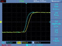
Hello, these parameters are not so difficult to get. Let me consider them and let me add time response. Blue is input signal, yellow pre output.
Attachments
Its something for me to shoot for.... find the circuit that uses the fewest number of transistors that can drive 30 ohms and be dc coupled/stable as well. While thd and s/n is under -100db. Doing it with open loop bandwidth of 20Khz (40KHz preferred). Now if I use different low noise transistors and cascode and the like, then what? But then I have made the circuit a lot more complex and not minimal number of transistors. I met my goal. Would like to see equal or better in all same areas. So far only Scott has risen to the challenge with a great opamp circuit. Lets see your minimalist super circuits. Final data has to be from working circuit not sim. In case of tie (?) the circuit with the fewest transistors wins the gold metal. Thx - RNM
Last edited:
John,
And anyone else who wants to answer this question. My question is are any of the proposed circuits that you are showing here actually circuits that you would use in anything but a challenge here to use the least amount or limited amount of discrete transistors. Or is this more like reading Cordell's book on amplifier design and this will technically meet the challenge but in reality to make it a viable product you would have to start adding more devices to make it actually functional for the purpose? I am just curious as to the intent for the design, if it is more than an intellectual challenge.
Steven
Its something for me to shoot for.... find the circuit that uses the fewest number of transistors that can drive 30 ohms and be dc coupled/stable as well. While thd and s/n is under -100db.
Dick, I'm afraid I have to stick with +24dBu output. There are no general purpose amplifiers specified at 1V out only. The JE990 and all available discrete op-amps I can find are specified at 20V p-p out. Professional mixing boards in general use 24V rails and the amplifiers are expected to drive 600 Ohms to near the rails.
There's nothing wrong with a headphone amp that's as loud as you would ever want at 1V, but it is fairly narrow in scope.
Before we build I have one more set of suggestions, that I will get to tonight.
Last edited:
Why not try a variation of this circuit as well, Richard? A few resistor changes, and it should be OK.
Lots of junction capacitance at the Vas output, wouldn't a buffer on the MOSFET gates help?
John,
And anyone else who wants to answer this question. My question is are any of the proposed circuits that you are showing here actually circuits that you would use in anything but a challenge here to use the least amount or limited amount of discrete transistors. Or is this more like reading Cordell's book on amplifier design and this will technically meet the challenge but in reality to make it a viable product you would have to start adding more devices to make it actually functional for the purpose? I am just curious as to the intent for the design, if it is more than an intellectual challenge.
Steven
This was not intended as an intellectual exercise in the beginning. After some output stage work I think I can reach (at least) my original goal, a discrete FET input general purpose op-amp with performance as close as possible to the JE990/OPA627/37 when used in the same circuits using almost as few transistors as the JE990 so it fits on a small card. A plus would be an all tiny SMT version.
I would also hope to build and measure a prototype.
laying down some specs -
Thats fine with me.... any level output as max but for apple to apple comparisons we can standardize on ref level of 1 volt into a load Z. And, at +24dbu also if you like as an option. I would not want to limit the discrete design to a level where IC's already can do the job. Like 600 Ohms. here, its more for the Highest-End consumer's applications.
Anyone else want to compete with their design? I put a circuit topology up that wasnt optimal for pro use but gives some good numbers as built and has good features to start things going. Remember your entry has to get built and tested and not a sim only. This is, after all, a DIY site not a tech journal. Thx - RNMarsh
Dick, I'm afraid I have to stick with +24dBu output. There are no general purpose amplifiers specified at 1V out only. The JE990 and all available discrete op-amps I can find are specified at 20V p-p out. Professional mixing boards in general use 24V rails and the amplifiers are expected to drive 600 Ohms to near the rails.
There's nothing wrong with a headphone amp that's as loud as you would ever want at 1V, but it is fairly narrow in scope.
Before we build I have one more set of suggestions, that I will get to tonight.
Thats fine with me.... any level output as max but for apple to apple comparisons we can standardize on ref level of 1 volt into a load Z. And, at +24dbu also if you like as an option. I would not want to limit the discrete design to a level where IC's already can do the job. Like 600 Ohms. here, its more for the Highest-End consumer's applications.
Anyone else want to compete with their design? I put a circuit topology up that wasnt optimal for pro use but gives some good numbers as built and has good features to start things going. Remember your entry has to get built and tested and not a sim only. This is, after all, a DIY site not a tech journal. Thx - RNMarsh
Lots of junction capacitance at the Vas output, wouldn't a buffer on the MOSFET gates help?
Scott,
There are a number of complimentary FETs from Fairchild in SO8 and Super SOT packages with Crss in the 65-100 pf range. Do you have an off the cuff figure of merit that might mitigate your concerns there?
Dave
Thats fine with me.... any level output as max but for apple to apple comparisons we can standardize on ref level of 1 volt into a load Z. And, at +24dbu also if you like as an option. I would not want to limit the discrete design to a level where IC's already can do the job. Like 600 Ohms. here, its more for the Highest-End consumer's applications.
Anyone else want to compete with their design? I put a circuit topology up that wasnt optimal for pro use but gives some good numbers as built and has good features to start things going. Remember your entry has to get built and tested and not a sim only. This is, after all, a DIY site not a tech journal. Thx - RNMarsh
What about testing at a couple of selected load levels, 600R and something higher - say in the 10k to 47k range, publish distortion vs frequency, distortion vs voltage out. Testing at lower loads can certainly be optional if desired. We could potentially test noise, offset, PSRR, CMRR, IMD, open loop, other performance??..
I plan to build and test some SE and class A varieties. Not sure that they will compete on level with the monolithics Scott mentioned but they have been simulated and waiting for some impetus to build them for far to long. I'll come along for the ride.
Dave
What about testing at a couple of selected load levels, 600R and something higher - say in the 10k to 47k range, publish distortion vs frequency, distortion vs voltage out. Testing at lower loads can certainly be optional if desired.
Dave
The distortion is lower at high Z for any circuit and is not a taxing load that would challenge any designer. it must be able to also do lower Z at low thd than IC opamp/IC buffer combo. Or what's the point -- just use an IC. -RNM
The distortion is lower at high Z for any circuit and is not a taxing load that would challenge any designer. it must be able to also do lower Z at low thd than IC opamp/IC buffer combo. Or what's the point -- just use an IC. -RNM
No misunderstanding there. The 600 ohm load is included in my list for testing, just as Scott advocated also. I am interested in what effect output loading has vs. other contributions to distortion so having the second, high impedance load data can be illuminating.
The point for me is an interesting challenge as part of a hobby that I enjoy. The genisis of this thread was after all a discrete, low parts count op amp that approximates the performance of ICs, correct? (paraphrased, not quoted)
I have no objections to testing of other loads interesting to you if a design/designer can do so. I will have to add some bias and have some other thermal considerations with the parts I am using.
If your desire is to compare the circuits here into headphone loads let's specify a standard set of loads to test as optional additionas to the op amp centric loads. 15, 30, 60 150, 300, and 600 ohm cover pretty much everything but electrostatics, correct? Want to add a reactive component to the load to verify low-z stability further?
Dave
If comparison of the various circuits presented here is the desire we should define gain setting for reporting as well at each load impedance. How about 1, -1, 10, and 100 for op amp versions?
1 and 4 for headphones?
Testing and reporting becomes quite burdensome quickly!
Dave
1 and 4 for headphones?
Testing and reporting becomes quite burdensome quickly!
Dave
The distortion is lower at high Z for any circuit and is not a taxing load that would challenge any designer. it must be able to also do lower Z at low thd than IC opamp/IC buffer combo. Or what's the point -- just use an IC. -RNM
There are any number of IC ADSL drivers that drive headphones just fine. Our own jcx has published designs and there is at least one commercial product. The data sheet specs are not audio based but much more brutal, Rload = 10 Ohms, Vo = 6V, f = 100kHz and still -90dBc there are several that easily drop to -100dB or better into 30 Ohms.
Last edited:
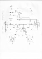
Kindhornman, the schematic I put up was designed for Parasound 18 years ago. We made prototypes then, but Parasound decided NOT to build this product, so this schematic has lain fallow for the last 18 years. I found it accidently this week in a manilla folder that I seldom look through.
However, just today I DID get a copy of Linear Audio Vol. 4. (Thanks Jan) and to my amazement, I saw virtually the SAME input and second stage (with small changes). I guess that Bob Cordell is on track! '-)
Perhaps when the time is right I can put the FIRST stage in, as well, as it is slightly different, and 3dB quieter, or so.
Anybody want to buy a slightly dated phono stage, that sounds pretty good, I have a prototype or two sitting around the lab. '-)
There are any number of IC ADSL drivers that drive headphones just fine. Our own jcx has published designs and there is at least one commercial product. The data sheet specs are not audio based but much more brutal, Rload = 10 Ohms, Vo = 6V, f = 100kHz and still -90dBc there are several that easily drop to -100dB or better into 30 Ohms.
The non-IC discrete here should do that and more, if possible -- Key to design for: be very simple -- use the fewest transistors. Low cost, easy to find parts. Drive low Z. No dc servo. wide OL bandwidth. THD and noise < -100db ref 1v. Gain at a range of 4-10X etal. Others can decide what more can be done by their design. -Thx RNM
- Home
- Source & Line
- Analog Line Level
- Discrete Opamp Open Design