Good enough! Looking forward to confirmation as well.…I'll get a noise measurement of it soon, but according to Dimitri they manage about 1nV/sqrtHz.
Your right. Easy to overlook the obvious connection shortcoming with the other apparent virtues of the 2sk2145.…Until NXP is persuaded to make a BF862 dual (and the latter was developed for AM radios, so the prospect may be unlikely) they are very attractive.
I was thinking vertically in that circuit. Delete the degen resistors and save the space by using two K2145s instead of four with the BF862.
Absolutely. How well can a simple circuit work as a functioning op amp. Judging each on these secondary effects is just as important as they may overshadow the primary performance metrics if not measured and understood for a particular use or implementation.Now you are getting practical! These other aspects are often viewed as an afterthought, some of which that can be brushed aside by invoking a better power supply etc. Considering them at or near the outset is wise.
For JFET diff pairs in small footprint circuits I have been looking at simple folded cascodes using MMBFJ111 JFETs with Vgs thresholds in the 6 volt range. Any suggestions?Another consideration is to look throughout, especially near the input stage, at how much signal swing changes power dissipation, i.e., thermal distortions, and also how the design responds to more-than-zero source impedance. And --- how does it handle overloads?
Overlaod recovery, clipping behavior, assymetrical clipping - all good points to consider. So are possible shorted outputs during cable changes... pop then smoke???

Thank you. Been looking at variations of it for a while and like it for its simplicity. This and several of the other examples posted can be made pretty small.Dave, I found your proposal very interesting.
This one from Scott was specifically what I was suggesting parts for.But now, what circuit are you talking about?
Several circuits recently. It really has been all over the place since starting.Generally, are we talking about several circuits, every one heading for another direction?
Just my opinion but I think we should build a number of them then test to see how well things really work. Patrick (EUVL) is working on a version of this Kaneda/Constellation like circuit. I have a layout in progress of my SE circuit. Scott's and others deserve some solder at some point as well.
I hope that others will build more of the proposed circuits. Some of these have little chance of fitting on a dip8 footprint like Patrick’s and mine so the API 2520 footprint could be used instead for ease of comparison...
Dave
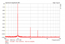
Got a bunch of J113s from Mouser, did a (not so) quick selection and tested again the design in #451 (with some major changes - no cascoded input fets: I'm a lazy guy ). This, besides reminding me why I really don't like designs requiring selected devices, makes me wonder wonder if the results are worth the time spent (well, not that long - 1 hour or so, but it was pretty boring, and I'm so lazy...): THD is now 0.0013% @ 0 dBV into 30 ohm in the 100 Hz - 10 kHz range, low order only (2nd & 3rd), BW is ample and DC drift just absent or so (output offset changed by less than 1 mV over 2 hours) - same operating conditions I described in my previous post. Quite a remarkable result for a 10 devices design with a far-from-optimum layout (still breadboarded, I mean); but I'm pretty sure I can't hear THD in the 0.005% range, so my somewhat philosophical question is: I'm quite happy to lower further an already pretty low THD figure by selecting devices, but maybe trying to design a circuit which doesn't rely on selection to perform well is a better approach - isn't it? To me, at least: all in all I'm not an audio professional, but an experimental physicist - have to throw in the circuit a bunch of randomly selected fets and see what happens, and if I can manage to hear any difference at all...
Ciao,
L.
). This, besides reminding me why I really don't like designs requiring selected devices, makes me wonder wonder if the results are worth the time spent (well, not that long - 1 hour or so, but it was pretty boring, and I'm so lazy...): THD is now 0.0013% @ 0 dBV into 30 ohm in the 100 Hz - 10 kHz range, low order only (2nd & 3rd), BW is ample and DC drift just absent or so (output offset changed by less than 1 mV over 2 hours) - same operating conditions I described in my previous post. Quite a remarkable result for a 10 devices design with a far-from-optimum layout (still breadboarded, I mean); but I'm pretty sure I can't hear THD in the 0.005% range, so my somewhat philosophical question is: I'm quite happy to lower further an already pretty low THD figure by selecting devices, but maybe trying to design a circuit which doesn't rely on selection to perform well is a better approach - isn't it? To me, at least: all in all I'm not an audio professional, but an experimental physicist - have to throw in the circuit a bunch of randomly selected fets and see what happens, and if I can manage to hear any difference at all... Ciao,
L.
Attachments
Last edited:
Perhaps not DIP8 footprint on a single board, but one can make a layer cake and get a lot more parts down if needed.I hope that others will build more of the proposed circuits. Some of these have little chance of fitting on a dip8 footprint like Patrick’s and mine so the API 2520 footprint could be used instead for ease of comparison.
Dave
It will reduce "series noise" (aka "voltage noise") and increase "parallel noise" (aka "current noise"). With FETs there is very little of the latter at audio frequencies, so it can help IF you can tolerate the increased capacitances.Not sure, but I thought I had read somewhere that paralleling input devices reduces noise?
_-_-bear
Perhaps not DIP8 footprint on a single board, but one can make a layer cake and get a lot more parts down if needed.
Absolutely right. I have some layouts like that. Truth be told, a few were fixes once in production (not audio)... Some discrete amps use right angle boards for most of the components with the dip8 footprint simply for the transition to the standard pin locations.
The AP 2520 footprint was an easy (read more space) option without 3D construction so I brought it up. Dip8 interests me most so I foresee some vertical construction in my future.
> With FETs there is very little of the latter at audio frequencies,
> so it can help IF you can tolerate the increased capacitances.
Ergo the quietude of power mosfets with their many parallel cells.
(mentioned before, but I think a mostly unexplored avenue)
> IF you can tolerate the increased capacitances
> so it can help IF you can tolerate the increased capacitances.
Ergo the quietude of power mosfets with their many parallel cells.
(mentioned before, but I think a mostly unexplored avenue)
> IF you can tolerate the increased capacitances
Got a bunch of J113s from Mouser, did a (not so) quick selection and tested again the design in #451 . . . hear any difference at all...
Ciao,
L.
Nice result Coluke!

....THD is now 0.0013% @ 0 dBV into 30 ohm in the 100 Hz - 10 kHz range, low order only (2nd & 3rd).....
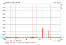
coluke, what kind of distortion figures/spectrum do you get OPEN LOOP?
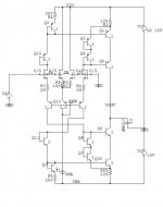
OK, here's one more. Folks asked about subing PNP's for the PFET's, this is one choice using the Rush cascode. The diode connected transistors could be substituted by diodes in most cases. Again use any output stage you like Dick's CF pair or triple-darlington or whatever. The ccomp and the degeneration in the input can be varied for different applications. I think with care this can do anything the OPA627/37 can do. With BF862's we have about $2 in devices.
Attachments
OK, here's one more. Folks asked about subing PNP's for the PFET's, this is one choice using the Rush cascode. The diode connected transistors could be substituted by diodes in most cases. Again use any output stage you like Dick's CF pair or triple-darlington or whatever. The ccomp and the degeneration in the input can be varied for different applications. I think with care this can do anything the OPA627/37 can do. With BF862's we have about $2 in devices.
The jFEts with 100 Ohms in the sources -- is that for CMRR improvment?
Thx - RNM
OK, here's one more. Folks asked about subing PNP's for the PFET's, this is one choice using the Rush cascode. The diode connected transistors could be substituted by diodes in most cases. Again use any output stage you like Dick's CF pair or triple-darlington or whatever. The ccomp and the degeneration in the input can be varied for different applications. I think with care this can do anything the OPA627/37 can do. With BF862's we have about $2 in devices.
Me likey
The jFEts with 100 Ohms in the sources -- is that for CMRR improvment?
Thx - RNM
That's DC bias, sets the current.
RNMarsh said:source resistors - makes matching more critical but THD and Noise is lowest - purist approach
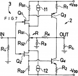
That what this Pioneer patent is said to address
US4356453.html
"Accordingly, an object of this invention is to provide a grounded-source type field-effect transistor circuit in which the source resistance is minimized to minimize the thermal noise in the circuit and to increase the circuit gain."
Adds more devices though.
rgds
james
Attachments
That what this Pioneer patent is said to address
US4356453.html
"Accordingly, an object of this invention is to provide a grounded-source type field-effect transistor circuit in which the source resistance is minimized to minimize the thermal noise in the circuit and to increase the circuit gain."
Adds more devices though.
rgds
james
It can be seen in Pioneer A09 amp, excellent amp of late 80s and 90s. Some seem to think the idea is new.
That what this Pioneer patent is said to address
US4356453.html
"Accordingly, an object of this invention is to provide a grounded-source type field-effect transistor circuit in which the source resistance is minimized to minimize the thermal noise in the circuit and to increase the circuit gain."
Adds more devices though.
rgds
james
Looks like they used two current sources to increase the drop in the source resistors, i.e. more offset range with smaller resistors. Smaller resistors = less noise. The current sources are not in the signal path and can be made to not contribute noise (heavy degeneration). This trick also works in output stages to make the Vas current and output bias independently trimmable.
On another point, if you look at the ideal JFET equations you will see that the cancellation of the quadratic term requires both Vp AND Idss to be the same. This would require exact complimentary pairs not just Idss selection.
Last edited:
- Home
- Source & Line
- Analog Line Level
- Discrete Opamp Open Design