1. If I were building in high volume, i would have the devices sorted/graded at the factory. And, with cheap labor used, the final batch can be quickly determined. This would be true with any complimentary jFET used.
Good luck, that is generally frowned upon these days and would be a huge premium. The best you get now is buy lots and maybe we'll take back the rejects. It's not like you can pair off any of them the Vp range is huge and the ones at 4-6V just are impracticle to use.
You would definately be better off buying a million pieces for 25-30K and doing it yourself and eating the rest. You could always bag them up and sell them on eBay.
-100 db of 2-3 order without negative feedback? Impossible.
There's lots of feedback there just no servo. I see the 1V @ 1kHz now, I was thinking more 20V p-p at 20kHz for -100dB at G = 26dB.
. The best you get now is buy lots and maybe we'll take back the rejects.
You would definately be better off buying a million pieces for 25-30K and doing it yourself and eating the rest. You could always bag them up and sell them on eBay.
Fine. Do that then. I did not find it a problem getting them on eBay and I didn't find it took long to match them from the 100 pc I bought. Got way more matched pair than i needed. I'd use the cheap labor available for such work. Probably do some test automation for sorting. Its all do-able.
[I get the point - but 1 million pieces is exagerated and far more than needed for the numbers talked about... that would net me 200,000 matched pair! Cost more like $2-3K worth. Again, very do-able.]
Last edited:
There's lots of feedback there just no servo. I see the 1V @ 1kHz now, I was thinking more 20V p-p at 20kHz for -100dB at G = 26dB.
1-2 volts rms will drive anything. What needs 20v p-p? Is that somehow a strength feature?
If using it as a line stage after a phono preamp then maybe 20+ db gain is needed. In the digital equipment (ADC/DAC/CD/DVD) and power amps used today, such gain isnt needed.
But no problem tweeking it for other outputs or gain or fb etc.
Last edited:
-100 db of 2-3 order without negative feedback? Impossible.
probably true.... but I never said that: w/o High gnfb and with wide open loop bw for the audiophiles was a goal.
Last edited:
probably true.... but I never said that: w/o High gnfb and with wide open loop bw for the audiophiles was a goal.
Your amp actually have that High gnfb. But it is fine, since open loop bw is wide enough for high gnfb on 20 kHz; what is bad when it is low on 20 kHz, even if very high on 10-100 Hz..
Your amp actually have that High gnfb. But it is fine, since open loop bw is wide enough for high gnfb on 20 kHz; what is bad when it is low on 20 kHz, even if very high on 10-100 Hz..
Well it is relative to opamp open loop gain of 100+ db's at 10Hz.... makes my circuit look like mid-level amount. Not low nfb but not high either.
Note: It wasnt developed as an 'op-amp' competitor for this forum. It's a somewhat different animal. It was for a different project last year. I threw it up here... mostly to show the zero TC and 'audiophile' specs and features they like. Its actually over-kill for my appl but its hard to make a bad performing circuit from a good topology.
Last edited:
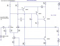
How about a simple circuit with an SE output stage...
I'm guessing that this Kaneda-inspired topology will perform/sound better with just 7 actives, although it's arguably 3-stage if you count the output CFPs as two stages. It will also work fine with a BJT LTP.
Attachments
-100 db of 2-3 order without negative feedback? Impossible.
Depends.
From Stereophile Measurement:
Ayre KX-R, spectrum of 1kHz sinewave, DC–10kHz, at 2V balanced into 100k ohms (linear frequency scale; left channel blue, right red).
For sure, it has no GNF.
Of couse, it will not be this performance into 30 Ohms, if you're not going to increase bias currents.
Attachments
![1108KXRfig4[1].png](/community/data/attachments/282/282185-69617c80a4c9459101ba68e491ce85e8.jpg)
-100 db of 2-3 order without negative feedback? Impossible.
Never say never
") - current-mode open-loop topologies are indeed capable of very low THD: I've built and tested a HP amplifier based on a pretty standard architecture (diamond in - transimpedance gain stage - high current diamond out) whose THD is in the -100 dB range (low order only) @ 1 kHz, 0 dBV into 30 ohm. And it sounds very good, too , but it is by far too much complex to be mentioned here (about 20 BJTs - basically a discrete CFA). You can easily convert it to closed-loop, and that's the reason why I gave a try to this architecture.
- current-mode open-loop topologies are indeed capable of very low THD: I've built and tested a HP amplifier based on a pretty standard architecture (diamond in - transimpedance gain stage - high current diamond out) whose THD is in the -100 dB range (low order only) @ 1 kHz, 0 dBV into 30 ohm. And it sounds very good, too , but it is by far too much complex to be mentioned here (about 20 BJTs - basically a discrete CFA). You can easily convert it to closed-loop, and that's the reason why I gave a try to this architecture.I think the Ayre KX-R is based on the same concept.
L.
[...]
I think the Ayre KX-R is based on the same concept.
L.
Input is J-Fets, gain stage is cascoded current mirrors. I don't know the output stage architecture though, but it seems to be a complementary JFetfollower. And balanced from input to output.
Charles Hansen in his posts leaved enough information to second guess, together with some magazine / website information ans pictures.
Check out the simplified (and strangely drawn) schematic here.
We're back to "this probably sounds better" and the sound of feedback vs no feedback, amply covered in other in other threads.
Nope, Scott - didn't mean to cover once more the 'sound of feedback' topic, just described the reason why I tried that specific topology. Actually I've never been able to hear any difference between CL and OL version of the amplifier, provided the output impedance of the OL version is very low (say < 1 ohm).
L.
That was meant in a more general sense. My original thought was along different lines like something that could be droped into a standard op-amp I/V or the Pacic-Pre phono. Keep it simple enough anyone can try it, nothing ventured nothing gained. Weather it uses 50 cents or $1.25 in devices was not the point.
Never say never
I think the Ayre KX-R is based on the same concept.
L.
Many of the topologies developed over the years for oscilloscope vertical amplifiers have very low distortion without global feedback. Feedback would have limited the frequency response. For a good coverage of many see Doug Feucht's book Handbook of Analog Circuit Design. The material has appeared here and there, including John Addis' contribution to one of the Jim Williams compendia, but afaik not as extensively in book form as Feucht's.
Translinear circuits with bipolars, which rely upon their very predictable characteristics, are routinely capable of order -80dB performance over a useful range of currents, and without additional local feedback (which improves things but slows them down). Barrie Gilbert is the foremost authority on these techniques, exploited in his eponymous multiplier.
I presented a current mirror in another thread that shows how to use cascoded FETs and floating bias sources with local feedback to realize low noise and distortion. It costs volts and power dissipation, but works well. It was to some extent offered for those who spurn bipolars, believing that there is some intrinsic inescapable "sound" there that they don't like.
For a good coverage of many see Doug Feucht's book Handbook of Analog Circuit Design. The material has appeared here and there, including John Addis' contribution to one of the Jim Williams compendia, but afaik not as extensively in book form as Feucht's.
Correction: Dennis Feucht, not Doug.
OP-Amp design
I also thought that was the point of coming to this forum as it was your input to do a new design (other than JC's) we (I) waited for and you delivered a very good one.
Has it now morphed into something else? Or, is it when a forum is done, it doesnt know how to end so it rambles on?
There are now plenty of Current-mode feedback designs being made on this DIYAUDIO and other sites. So there needs to be a goal for us to shoot for and not just ramble on about this or that circuit.
What are the goals for a new design?
Personally, I would now like us to try matching the performance of an opamp's high feedback with one with no gnfb. There are not many out there. Make it popular and easy as possible to make as the new goal.
My original thought was along different lines like something that could be droped into a standard op-amp I/V or the Pacic-Pre phono. Keep it simple enough anyone can try it, nothing ventured nothing gained.
I also thought that was the point of coming to this forum as it was your input to do a new design (other than JC's) we (I) waited for and you delivered a very good one.
Has it now morphed into something else? Or, is it when a forum is done, it doesnt know how to end so it rambles on?
There are now plenty of Current-mode feedback designs being made on this DIYAUDIO and other sites. So there needs to be a goal for us to shoot for and not just ramble on about this or that circuit.
What are the goals for a new design?
Personally, I would now like us to try matching the performance of an opamp's high feedback with one with no gnfb. There are not many out there. Make it popular and easy as possible to make as the new goal.
Last edited:
PS - On the mid-level of gnfb circuit without dc servo... some have wondered just how stable over the long term it could be. After a year of service, I measured the dc offset at the output again and it is exactly where i left it a year ago..... .00x + or - a couple mV. -RNM
Richard, in your Linear Audio article, Table 1 shows an entry for signal-to-noise ratio with the input shorted of - [sic] 135dB. Is this for a reference level of 1V rms at the output, into 30 ohms?PS - On the mid-level of gnfb circuit without dc servo... some have wondered just how stable over the long term it could be. After a year of service, I measured the dc offset at the output again and it is exactly where i left it a year ago..... .00x + or - a couple mV. -RNM
- Home
- Source & Line
- Analog Line Level
- Discrete Opamp Open Design