Scott's posting #135 and the related circuitry is a beauty.
Unfortunately the component count is high.
And most DIY enthusiasts would struggle with a discrete built of such high gain at 20kHz. Slowing down the dominant pole most likely would be necessary to ensure DIYability, unfortunately this impacts performance....
Nevertheless, to me it is the most educative circuitry of this thread IMHO,
thanks for that !!
I missed this one, thanks for having pointed it. I agree with your comments. I like to see Fets of one type only in the differential pair.
Last edited:
Here is yet another circuit for a discrete opamp. It has the front end of the AD797 opamp, but with a single ended Class A Mosfet output stage. This circuit can be varied considerably. The input devices can be Jfets, Mosfets or BJTs.
I use essentially the same floating current-mirror concept from the AD797 in the all-BJT LF03 discrete opamp. The current mirror is bootstrapped to about one Vbe drop below the output.
http://www.diyaudio.com/forums/analog-line-level/207871-lf03-discrete-opamp.html
I do cheat a little bit on the latest revision (lf03c), by using a few 1.25V reference diodes (which are actually monolithic band-gap references) for biasing. But the topology still works ok in simulation with the bandgaps substituted by a pair of 1N4148s or similar.
How does it sound? Very dark, detailed and airy - audibly trumps the OPA627 in the I/V stage of a Marantz CD4000.
Steven
I had not seen a hand held with that resolution of depth of field.
Steven, I have not seen one either.

These technical capabilities were for dedicated IR imaging devices and not for hand held IR spot thermometers. (And these were for entry level prof. Equipment available since 5 years. Today, with 1-2 zeros added on the check, one can have quantum IR-sterling cooled-sensors, 1us system response times, true radiometric calibration and precision and software with amazing capabilities).
You could also drill a hole as you stated and insert the thermocouple into that hole.
By drilling the hole you would appear to have two affects, one being the properties of the cavity depth to width and the second being a much thinner substrate that has a time lag in response to the actual temperature change internal to the device. Am I following what you are saying properly? Thanks again.
The hole works like a trap for IR (heat)radiation. Something like an insulated enclosure with a small hole on top.
The thermal capacity of the walls (material's mass) is much higher than that of the air inside the hole. Thus material temp. in effect dictates cavity’s air temperature (air standing still).
Calibrators for thermocouples -for IR spot thermometers as well- have such cavities (depth to d ratio is minimum 10)
I am glad you pointed out the fallacy of increasing the temperature…
It is not exactly fallacy.
It is valid when dealing with DC operating points in such situations:
Static –no signal-conditions
With sub-Hz AC signal
With HF only (say RF) signals.
My point had to do with dynamic conditions at audio frequencies and with audio signals.
Actually, that is not the case.***
Interchip dynamics will not change unless the gradient to the outside world is different for each chip. If for example, one die's heat must go past the other to get out.
***the astericks are because the thermal conductivity of silicon is temperature dependent, the eq is:
Kt =286/(T -100) for T =300 to 600K
Cheers, jn
Jneutron
I can not figure out in your post why this is not the case (we are talking “interchip thermal dynamics”)
Per the formula above, Kt decreases with increasing frequency.
What do I miss?
George
Jneutron
I can not figure out in your post why this is not the case (we are talking “interchip thermal dynamics”)
Per the formula above, Kt decreases with increasing frequency.
What do I miss?
George
You spoke of hotter temperatures changing the thermal response/deviation of the circuit because of the lower ability to transfer heat outside the system. This of course impacts the absolute temp of the junctions, but not the differential between chips, which is the discussion.
I did point out that silicon's thermal resistance/conductivity is a function of temperature, as is BeO's. Other than that effect, the thermal response of the system is not dependent on the sink temp, because the heat sources are not.
jn
How much emitter resistance is needed
to degenerate the gain of a 2n4401 down to
an (enhancement-version) 2sk170 ?
(since the enlightened know that bi-polars are voltage controlled)
I have very limited models for discrete devices so consider the 4401/4403 a place holder. What you mention above is not really necessary, the bi-polars are close to a simple 2:1 current mirror so the left and right sides of the input transconductance contribute equally to the output current in true push pull fashion. The voltage gain is developed only at the output. This is a simple difference from the usual use I have seen where there is only a large-ish resistor on the left side and the degeneration on the Vas is much smaller yielding two voltage gains in series.
I also think the Cdg of the JFET's will be much less of a problem without large voltage gain at the drain. In addition all the junctions balance so this stage is very thermally stable.
Sorry my symbol library does not even have a PFET symbol, luckily the model assignment fixes that. Also it was late, this is intended to drive the output stage of your choice to make a complete amplifier. I was simply saying that it at 20k even open loop there was low distortion and lots of gain left.
Last edited:
You spoke of hotter temperatures changing the thermal response/deviation of the circuit because of the lower ability to transfer heat outside the system. This of course impacts the absolute temp of the junctions, but not the differential between chips, which is the discussion.
I did point out that silicon's thermal resistance/conductivity is a function of temperature, as is BeO's. Other than that effect, the thermal response of the system is not dependent on the sink temp, because the heat sources are not.
jn
Indeed, it is a seductive but misleading notion per se to suppose that running warmer will reduce the importance of fluctuations. I see it stated without proof periodically, as if it were intuitively obvious, and it is not. IF the temperature coefficient itself were a strong function of absolute temperature then you would see an effect, whether beneficial of not clearly depends on the sign.
Another notion is the concern with dissipation that changes a chip temperature from, say, 25 C to 75 C, and then people start worrying about the increase in thermal noise. Since (for true thermal noise sources) the voltage or current noise is proportional to the square root of the absolute temperature, a change of that magnitude is only an increase in noise spectral density of about eight percent. Not welcome, but not horrible.
However, for other processes generating noise, like the shot noise in drain-gate leakage, the temperature dependence is strong, roughly doubling the leakage current every delta 10-12 K, and with that the midband current noise proportional to the square root of the current. When JFET opamps began to appear it was dicey to evaluate the actual bias currents at the inputs if you weren't sure how warm you'd be operating. Some manufacturers pointed out that some bipolar amps with teeny input stage currents and super-beta devices could beat the JFET amps at higher temperatures!
At the operating temperature of the photodiode array preamps (one per video line), near dry ice, the net input currents were about 1 and 3 fA. The devices were 2N4416s, run at about 6V Vdg, with Vgs about -100mV.
I also think the Cdg of the JFET's will be much less of a problem without large voltage gain at the drain. In addition all the junctions balance so this stage is very thermally stable.
In fact the voltage gain from input to drain is ~-1 just as in a cascode with like devices but here the current mirror configured as it is makes this voltage common mode at the drains so with balanced source impedance we will see little effect from Cdg. In essence there is not much gained by cascoding the input FET's as long as the DC gate current is not too compromised by Vdg. In lower gain voltage follower applications the common mode effects are more important but ballancing the source impedances for AC cmrr is still important.
Last edited:
I have very limited models for discrete devices so consider the 4401/4403 a place holder. What you mention above is not really necessary, the bi-polars are close to a simple 2:1 current mirror so the left and right sides of the input transconductance contribute equally to the output current in true push pull fashion. The voltage gain is developed only at the output. This is a simple difference from the usual use I have seen where there is only a large-ish resistor on the left side and the degeneration on the Vas is much smaller yielding two voltage gains in series.
I also think the Cdg of the JFET's will be much less of a problem without large voltage gain at the drain. In addition all the junctions balance so this stage is very thermally stable.
Sorry my symbol library does not even have a PFET symbol, luckily the model assignment fixes that. Also it was late, this is intended to drive the output stage of your choice to make a complete amplifier. I was simply saying that it at 20k even open loop there was low distortion and lots of gain left.
Scott,
Thank You for the answer, but you misunderstood my post
It had nothing to do with your circuit.
I would simply like to know how much emitter degeneration
it would take to make a 2n4401 have ~ the same gain as a
2sk170 ? I.E. Use degenerated bipolar complements to replace
the disappearing jfet complements.
I was being facetious. (I thought)But you have been educated on this subject - you yourself said that 'the enlightened know transistors are voltage controlled'
What little education I have
(USN Electronics Technician and Occupational electronics
(~ 30 years ago)) both used hfe as the main parameter
with bipolars. AND that xsistors are current controlled as
opposed to tubes being voltage controlled.
(I'm not arguing the point, only stating what I was taught)
hfe = delta Ic / delta Ib (IIRC)
re ~ 22 Ohm (small signal device)
input Z = re + (emitter resistor * hfe)
Last edited:
-noob allert-
Today got a new pre-amp and that always makes me highly interested in what exactly I have but knowledge is almost non existant I'm afraid. Still I hope it would be ok for me to post this here since this thread seems a good way to see if I 'get' some of the stuff discussed. (perhaps some credit for going through the whole thread?)
If this is not wanted and/or to OT just ignore please.
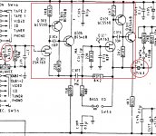
Anyway, attached a sniped of the pre-amp I acquired today (chuffed) and some questions.
a. The part in the red square is the discrete opamp (?)
b. The circeled parts are the DC coupling caps you all are wanting to avoid (?) (and thus this design would not fall in the wanted design category)
c. This must mean some sort of DC servo feedback stuff talked about a couple of pages back is non existant and the follow up question would be...
d. Why would the designer chooses for the DC coupling caps (quit a few in the whole design) is cost the only reason or are there more benefits of this design?
e. anything else you like to share, love to learn more!
Today got a new pre-amp and that always makes me highly interested in what exactly I have but knowledge is almost non existant I'm afraid. Still I hope it would be ok for me to post this here since this thread seems a good way to see if I 'get' some of the stuff discussed. (perhaps some credit for going through the whole thread?
)If this is not wanted and/or to OT just ignore please.
Anyway, attached a sniped of the pre-amp I acquired today (chuffed
) and some questions.a. The part in the red square is the discrete opamp (?)
b. The circeled parts are the DC coupling caps you all are wanting to avoid (?) (and thus this design would not fall in the wanted design category)
c. This must mean some sort of DC servo feedback stuff talked about a couple of pages back is non existant and the follow up question would be...
d. Why would the designer chooses for the DC coupling caps (quit a few in the whole design) is cost the only reason or are there more benefits of this design?
e. anything else you like to share, love to learn more!
Attachments
Last edited:
You spoke of hotter temperatures changing the thermal response/deviation of the circuit because of the lower ability to transfer heat outside the system. This of course impacts the absolute temp of the junctions, but not the differential between chips, which is the discussion.
I did point out that silicon's thermal resistance/conductivity is a function of temperature, as is BeO's. Other than that effect, the thermal response of the system is not dependent on the sink temp, because the heat sources are not.
jn
jh
I was talking of temp. differences that are building up between dynamically self heating (I*R) components which are inside the same IC chip. The same thing that you were referring too here:
2mv untrimmed...wait till you start finding thermal response issues in the 10 to 100 millisecond realm..then you'll come crying to the die people.
jn
I wanted to point out that these local delta T will increase when one decides to heat the whole IC in an attempt to control the DC drifts of the IC.
Is there an agreement on this?
(bcarso says yes
)Indeed, it is a seductive but misleading notion per se to suppose that running warmer will reduce the importance of fluctuations.
George
Hitsware, you're not far of the mark. For many decades, bipolar transistors were considered BETA DRIVEN devices. I spent my first 5 years designing with that approach.
It it worked pretty well, because in many, many applications, the design WAS beta driven. It is also true, today, more than many realize.
As betas increased from let's say 20 to 100, then to 200 or more in many cases, then Vbe became significant, AND the real gain of the circuit was not limited by beta, but by the intrinsic Gm. The intrinsic Gm is .04mhos/ma. It goes up or down directly, depending on the quiescent current through the part.
So, 1A would have a Gm of 40 Siemens (or mhos)
In the early 70's the professors decided that beta was just a parasite and every attempt has been to ignore it.
I was being facetious. (I thought)
What little education I have
(USN Electronics Technician and Occupational electronics
(~ 30 years ago)) both used hfe as the main parameter
with bipolars. AND that xsistors are current controlled as
opposed to tubes being voltage controlled.
(I'm not arguing the point, only stating what I was taught)
hfe = delta Ic / delta Ib (IIRC)
re ~ 22 Ohm (small signal device)
input Z = re + (emitter resistor * hfe)
That re is at about 1mA Ic, typically, (I usually use 26 ohms as a rule of thumb [edit: Curl above, 25 ohms]) and reciprocal to that current, to a point. So if you want to have the series external emitter resistor dominate the effective transconductance, make re relatively small (or simply reduce the current, but this may affect distortion negatively).
BTW, the noise contribution from that "resistance" is due to shot noise in the current referred to the input as a voltage noise density. Since the transconductance goes up directly with current and the shot noise goes as the square root, for low source impedances the overall noise goes down with increasing current, to a point that, among other things, is limited by the real thermal noise of the base spreading resistance. The contribution of the shot noise/transconductance makes the expression for the re contribution look like about that of a real resistor half the value of re, which is nice.
It's funny to see people using very-low base resistance transistors at moderately low currents. The Marshall Leach-style common-base MC stepup circuit is an example --- but in his defense, he was also interested in prolonging battery life.
Hitsware, you're not far of the mark. For many decades, bipolar transistors were considered BETA DRIVEN devices. I spent my first 5 years designing with that approach.
It it worked pretty well, because in many, many applications, the design WAS beta driven. It is also true, today, more than many realize.
As betas increased from let's say 20 to 100, then to 200 or more in many cases, then Vbe became significant, AND the real gain of the circuit was not limited by beta, but by the intrinsic Gm. The intrinsic Gm is .04mhos/ma. It goes up or down directly, depending on the quiescent current through the part.
So, 1A would have a Gm of 40 Siemens (or mhos)
In the early 70's the professors decided that beta was just a parasite and every attempt has been to ignore it.
JC, reminds me that Putzeys recently opined that triodes were the only real voltage-controlled voltage source
47 Ohm or 47 kOhm ?
I already apologized for the typo. I meant 47 Ohm, but if to consider non - zero emitter resistance and non - infinite beta 26 Ohm indeed would be closer. But input resistance will be no higher than 10K, so of course you can't substitute directly in all cases.
In the early 70's the professors decided that beta was just a parasite and every attempt has been to ignore it.
Fairly quaint way of putting it. Translinear circuits work even at beta of 1, oh well we've been over this before no need to repeat.
I have hilted in red the salient point we disagree on. The local delta T will not increase as the entire widgit increases in temperature.I wanted to point out that these local delta T will increase when one decides to heat the whole IC in an attempt to control the DC drifts of the IC.
Is there an agreement on this?
(bcarso says yes
George
The local delta T will be dependent on the heat flow between the components of interest, not on the absolute temp. As I pointed out, if the thermal conductivity between the local chips changes as a result of absolute temperature, so will the delta T between them.
I believe bcarso and I are agreeing, and we think differently from you.
Perhaps when I get the time, I could draw it up, verbal descriptions are not easy to express nor follow at times.
cheers, jn
-noob allert-
Today got a new pre-amp and that always makes me highly interested in what exactly I have but knowledge is almost non existant I'm afraid. Still I hope it would be ok for me to post this here since this thread seems a good way to see if I 'get' some of the stuff discussed. (perhaps some credit for going through the whole thread?
If this is not wanted and/or to OT just ignore please.
!
The JFET and two bipolars are a very high input impedance unity gain buffer that probably works pretty well, but is necessarily single ended and needs AC coupling. The high impedances allow smaller caps and larger resistors to be used so at least they don't have to be big electrolytics everywhere.
I have hilted in red the salient point we disagree on. The local delta T will not increase as the entire widgit increases in temperature.
The local delta T will be dependent on the heat flow between the components of interest, not on the absolute temp. As I pointed out, if the thermal conductivity between the local chips changes as a result of absolute temperature, so will the delta T between them.
I believe bcarso and I are agreeing, and we think differently from you.
Perhaps when I get the time, I could draw it up, verbal descriptions are not easy to express nor follow at times.
cheers, jn
George if you diagram it using (I know over simplified) the circuit analogy of input power as current, ThetaJ as a resistance, and temperature as voltage, you will see the point. Raising ambient ("ground") does not change the delta V's anywhere.
- Home
- Source & Line
- Analog Line Level
- Discrete Opamp Open Design