Come on... This ideas were implemented long before Wavebourn was born. For example, steam machines contained stabilizers of sped of rotation that used weights on springs.
That would be considered non-analogous art...
I think this was the big IGBT amps. DC coupled no servos and the IGBT's from Toshiba (short lived). Nice parts those IGBT's oscillations and thermal runaway.Well, you are going to stand alone with this, Richard. The VERY IDEA of not using a servo is artificial. The effort, in many examples, to eliminate either the servo or a feedback capacitor, is just too much to make the best possible audio quality.
Let me give an example:
About 15 years ago, I visited a company called Threshold, then located down in Southern California.
It was apparently the successor of Nelson Pass's Threshold.
They built a very formidable solid state power amp, that they INSISTED be DC coupled without a servo. What they had to do with parts selection and temperature controlled adjustment was FORMIDABLE! They put MORE effort in device selection for low drift than virtually anything else in the design. Then, they went out of business. Did not surprise me at all.
I think this was the big IGBT amps. DC coupled no servos and the IGBT's from Toshiba (short lived). Nice parts those IGBT's oscillations and thermal runaway.
Rich May once told me that the use of DMOS in the output stages of Sumo amps, when he was there at the time, was primarily a marketing decision.
New!! Improved!!

That would be considered non-analogous art...
Mechanical, chemical, biological control systems work on the same principles as electronic control systems. Electronic control systems include other aspects, for example thermal.
The potential problem with INTEGRATING the servo into the design, is that you get the SAME downsides of an external servo, without the ease in DECOUPLING the servo to really be just a DC offset control.
Only if you have a particular design you are thinking of. it can be done well.

Mechanical, chemical, biological control systems work on the same principles as electronic control systems. Electronic control systems include other aspects, for example thermal.
I was speaking from the perspective of my career as a patent examiner for the U.S. Patent and Trademark Office. In the patent world, they are considered not analogous. I would never look in steam engines for a control scheme of an opamp and it would never hold up upon appeal.
So, what you consider analogous is not what I consider analogous.
Come on... This ideas were implemented long before Wavebourn was born..
yes. so? You have added a way to impliment a servo in an amplifier circuit -- as i am asking for. Accept the credit/compliment.
I am interested in the practical application to a real audio amp circuit, of course. Can you show it in a working circuit so others can make it if you dont want to -- or at least talk in more detail about the proposed appl to a circuit which can have new ideas generated from it and so it can be applied to other toplogies.... [sorry got my manager hat on.] -RNM
Do you or anyone have an idea on how to do this to JC's favorite topology?
Last edited:
I am interested in the practical application to a real audio amp circuit, of course. Can you show it in a working circuit so others can make it if you dont want to -- or at least talk in more detail about the proposed appl to a circuit which can have new ideas generated from it and so it can be applied to other toplogies.... [sorry got my manager hat on.] -RNM
What I talk about, is basic. There are many ways to implement it. For example, take the majority of power amp schematics shown in Solid State forum, they all contain so called "Vbe multiplier", that is one transistor between bases of output stage (buffer). This "Vbe multiplier" is one example: it is in direct contact with an output transistor, and when it is heated by an output transistor it's Vbe drop decreases. It decreases voltage between it's collector and emiter, hat is applied as bias between bases of transistors of the output buffer, decreasing bias voltage that decreases idle current. Decreased idle current decreases temperature of output devices, henc temperature of the sensor that is Vbe multiplier in this particular case.
Similarly, as I described already few times, in that schematic that John posted, temperature of output devices can be sensed by diodes, or similar Vbe multipliers, and the result used as a voltage reference for the current source in the tail of the input diff-pair. What to draw here? It is all obvious. Also, please remember that I am lurking here from work computers that run Linux and can't install on them schematic drawing software.
This "thermal stability" discussion has nothing to do with the topology that Scott Wurcer presented. It is the parallel thread about "Practical Example" offered by John Curl few pages before, the reply to his question, how to improve the stability of the schematic. It is not intended to give you complete designed, breadboarded, and ready to manufacture opamp.
Hi Scott
I agree with everything you are saying here.
I think your circuit is the most interesting here so far.
I'll put it in to my simulator and have a closer look at it.
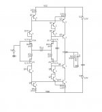
BTW: is this the model you are using for the BF862?
Cheers
Stein
I don't use the package parasitics here otherwise essentially the same.
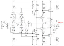
If for the moment we allow complimentary JFET’s there is complimentary symmetry on the circuit I posted. Here for those that are interested. Load the output with 90k and the open-loop BW is 20k while the OPEN-loop distortion is -70dB. I thought these things were good folk medicine for the sound. The triple-darlington is virtually no load to this and can be biased to drive a heavy load too. At 20k the base current re-capture lowers the open-loop distortion by 30dB.
Attachments
 Guys let's focus on all of the many very cool discrete op-amp designs being surfaced here. Thanks..
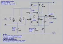
Here is yet another circuit for a discrete opamp. It has the front end of the AD797 opamp, but with a single ended Class A Mosfet output stage. This circuit can be varied considerably. The input devices can be Jfets, Mosfets or BJTs. The output could have a short circuit protection added if required. Offset correction could be added to vary the current through R5, R6.
It has been a year or so since I've modeled this circuit in detail, but it seems to work very well. THD is very low, and H2 dominant. Note that I haven't built one to actually test (and don't plan to). I've suggested suitable sot223 surface mount devices, but almost anything can be used. No unobtainable P channel Jfets are required! The compensation probably needs some work!
Paul Bysouth, August 2012
Attachments
- Home
- Source & Line
- Analog Line Level
- Discrete Opamp Open Design