how is dc output offset and drift again ?
No coupling caps (10mfd) anywhere and no dc servo?
-RNM
I dunno, let someone else build the model in their simulator and find out. I've done my part. This is supposed to be a collaboration after all.
Last but not least. I doubt that a simulation with standard models is the right tool to analyze distortions in the sub -80db range.
In my experience the sim helps to find the right direction and see the fundamental nature of the distortions. But in all my past simulate+build trials it turned out that the sim was much nicer than reality.
Agree that many succumb to "sweet Spice lies". And indeed, the Constellation-like amp is full of gotchas, although further analysis can elucidate them.
Among the mechanisms that are not usually well-simulated: actual JFET/DMOS behavior in the transition between low Vdg and "saturation", especially for very-short-channel devices; thermal effects on many parameters, especially in bipolars, and FETs operated far from their intrinsic low temperature coefficient region. Thermals are particularly nasty for designs with low loop gain. And they are very difficult to model, involving a number of time constants.
Many tout the bipolars with flat beta (the popular misnomer is "linear beta"). But when, in virtually any application, the chip temperature is varying with changes in collector current, the shift due to that is making the beta flatness a bit irrelevant.
And of course the intrisically perfect matching among devices is very misleading, although once aware of this one can create models with intentional amounts of mismatch and see the effects.
In addition, simulators are capable of giving poor answers if the time step sizes for transient response (and from which Fourier estimates are derived) are too large. As well, most of the Fourier maths are based on the assumption that the last full cycle of a sim is on "forever". Thus, if something is still settling within the circuit, giving a tilt for example to the waveform, you will get pessimistic answers. If you see a spectrum with little difference between successive harmonics check to see if there is a long time constant process within the circuit, or at least make the simulation record longer and note the effects.
I've been blessed (!) with a buggy program that frequently requires patching around defects. I have a set of multistage narrowband notch filters that can be run alongside the Fourier as a sort-of-reality check, for example.
Another error that pops out is when one looks at Bode plots in an attempt to adjudge power supply rejection (for example). If, as a current generator is being compensated for better PSR, the dominant effect is to have mostly a second harmonic residual appear from the power supply modulation, Bode will give very misleading results. Transient response in such cases is essential.
Having said all that, I've gotten good agreement over the years with what is built. Yes, the more modest designs and minimal-parts ones are easier to measure and the correspondence better. Actually, with the repertoire of structures available in the "toolbox" now, the problem is more in the analyzer's capability.
One could say at that point "Who cares?" And I would to an extent agree. But coming from an instrumentation background, there are places where higher performance may be useful, and therefore still of even practical interest. Perhaps there should be a diyinstruments.com .
I dunno, let someone else build the model in their simulator and find out. I've done my part. This is supposed to be a collaboration after all.
That's the spirit! ... Just kidding ya
Nice circuit.A DC servo addition would be nice. If not would probably want a cap at the output. DC can be dangerous to speakers as I'm sure you know.
Brad,
> Speaking now of the Constellation-like simplified schematic from JC's post #168:
I spiced essentially the same circuit late last night but use 2SK117, which is essential identical to one half of a 2SK2145.
I use 750R for R3, and 1k for R4 & R5.
Closed loop bandwidth for gain of +2 and -1 are all over 10MHz.
Too much gain at HF. So need a Zobel somewhere.
Only first shot. Some way to go.
Need to get proper models from Toshiba.
Cheers,
Patrick
Although I suspect the duals from LIS are fine, I am intrigued by the Toshibas. I checked last night and see that they are listed on the Toshiba America site, which means that with any kind of luck they may even be stocked by some distributor (alas, neither Mouser, Digikey, nor Newark have them). I need to get my hands on them to see if there are no nasty parasitic diodes lurking within which sentences one to use as only a long-tailed pair (or grounded sources connection).
the DC detect would be adequate at the input and/or output of the Power Amplifier.That's the spirit! ... Just kidding ya
A DC servo addition would be nice. If not would probably want a cap at the output. DC can be dangerous to speakers as I'm sure you know.
the DC detect would be adequate at the input and/or output of the Power Amplifier.
Yeah, that would be fine, if you want to trust that your amp has a DC protect circuit. Not all commercial amps do. I've had two commercial amps go DC at the output and destroy speakers.
I find that many of these 'qualifications' compromise the final result. You know, few fets, few active parts, 30 ohm drive, no factory matched parts, no servo, etc., etc.
2n3819, my word! '-)
It seems that every time someone makes a contribution, another utters a complaint.
I'll tell you a secret: IF you can't use decent, first class parts, it would be better to use an IC. That's what I did with the JC-3 phono stage! It now has an A rating, so it can be done.
2n3819, my word! '-)
It seems that every time someone makes a contribution, another utters a complaint.
I'll tell you a secret: IF you can't use decent, first class parts, it would be better to use an IC. That's what I did with the JC-3 phono stage! It now has an A rating, so it can be done.
Nice
Those caps are there just to squeeze out a few more dB of loop gain at HF - with 10 nF or so loop gain is flat up to 20+ kHz, although not that high (52 db approx). In principle you can use larger caps to get even higher loop gain, but since THD seems to be already in the -120 dBc range at mid freqs, this is probably unnecessary. Maybe substituting R16 & R17 with a couple of LEDs, or a diode string, could yield the same results without caps - have to try.
@dirk: nice job
@rnmarsh: DC offset and drift seem to be quite small, even without coupling caps both in the signal or feedback paths - have to set up a prototype to check how real devices will work.
@john curl: John, I know there are far better devices than the ones employed in the sim, but I just want to try with these poor-man parts and see what happens
. I mean: I'm just getting sick of spending my time searching for pretty standard unobtainable devices - I'm just having a look at the 1982 SILICONIX FET Design Catalog: its FET Cross Reference and Index is a 12-pages long list; nowadays even getting a stupid 2N5457 can be a nightmare...L.
....ok, looking at the circuits in posting 273 and 279.
I agree that my previously proposed folded cascoded circuit has not enough gain. So using the VAS to get gain is making sense.
Also I agree that a diamond buffer is hard to beat with two J-Fets, also with two MosFets.
From my side no complaints to spend the 4 BJTs for the output stage.
..erhm, and now I have to utter (sorry John).
*uttermodeON*
@dirkwright:
I am wondering about the CCL3.5 in the simulation.
Are this current sources?
If so, we have to take care. In real life the VAS will suffer from the tolerances of the DC-current gain and from the systematical imbalance of DC gain between PNP and NPN and from the temperature dependency of the DC gain.
I think the set up of Coluke is more practical here, even when it has slightly less gain.
@John:
World class components, that's a concern.
But it is not easy to get 2SK170 and 2SJ108 or 2SK370 and 2J74 (of course only V rating acceptable) these days and if you get it at all, you really pay for it. In fact I appreciate much more to see a sim and measurements on a real set up of with average components, rather than just seeing a sim with high end components and insufficient models and misleading sim results and without connection to reality.
I am glad to see that coluke intends to work on it in reality, same it was nice to see EUVL jumping in a potential layout for playing around for the quasi complementary circuitry.
*uttermodeOFF*
Overall it looks like there are fundamentally two favorite circuits, which are 'in work' by different people.
Looking forward to see the outcomes
If you can't get the parts, find a good IC.
For the record, I did a simple Google search for two complementary jfets, the J113 and the J175. I found both of them for sale under $0.50 each. You just have to buy a bunch of them and select them out. If you cannot invest $100 for this, then buy an IC. It will give you better performance.
For the record, I did a simple Google search for two complementary jfets, the J113 and the J175. I found both of them for sale under $0.50 each. You just have to buy a bunch of them and select them out. If you cannot invest $100 for this, then buy an IC. It will give you better performance.
In fact I appreciate much more to see a sim and measurements on a real set up of with average components, (...)
Agree
- then I think you're going to appreciate the open-loop CF amp I'm talking about in this post: http://www.diyaudio.com/forums/head...eadphone-amp-linear-audio-24.html#post3045721Too many bjts to be mentioned here, but it works really fine with pretty standard and cheap * unselected * devices, and this was exactly what I was looking for.
L.
Now why did I choose these devices? They are representative of still available devices that can still be purchased, that Levinson used in the early days. OF COURSE, the Toshiba devices are easier to match, lower noise, and higher Gm. But if you can't get ANYTHING (Toshiba jfet), then alternatives should be chosen.
Last edited:
That's the spirit! ... Just kidding ya
A DC servo addition would be nice. If not would probably want a cap at the output. DC can be dangerous to speakers as I'm sure you know.
I think the spec was for less than 2mV of DC offset, wasn't it? I can't remember.
This isn't my show, I just wanted to make a contribution, however small it may be.
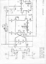
This is a recommended alternative to a complementary differential fet design. This design was used in several professional mixers as well as in three 30ips master analog recorders.
sorry about the bad copy, the original schematic goes back to about 1977.
sorry about the bad copy, the original schematic goes back to about 1977.
Attachments
If you can't get the parts, find a good IC.
For the record, I did a simple Google search for two complementary jfets, the J113 and the J175. I found both of them for sale under $0.50 each. You just have to buy a bunch of them and select them out. If you cannot invest $100 for this, then buy an IC. It will give you better performance.
These can be considered ' complementary ' ?
http://www.fairchildsemi.com/ds/MM/MMBFJ177.pdf
http://www.fairchildsemi.com/ds/J1/J111.pdf
- Home
- Source & Line
- Analog Line Level
- Discrete Opamp Open Design