By exploiting the use of floating power supplies, to which EUVL has gotten me momentarily addicted after I started looking at his IV threads, and with RM's allowance for cascodes and current sources not counting, I have a crazy design for the opamp that uses six transistors. But two to four floating voltage sources (one to three of which could be primary batteries as there is virtually no current), a very asymmetrical-looking input stage... If all one needs is an inverting input the thing gets much simpler and the floating V source that actually supplies real current goes away.
When I have convinced myself I understand it I'll present it. It does use the buffer I showed, and counts that as four devices (the two current sources being exempt).
Of course I'm not doing this to meet the eight transistor limit, but I'm amused that it may be possible. I don't believe it will sound better on account of the lower number.
I think this may illustrate somewhat:
http://www.diyaudio.com/forums/solid-state/189123-anyone-built-power-diamond-buffer-amp.html
.....
I am led to believe that this is Chris Paul's work, and was perhaps published in a mid 80s (?) audio amateur if not elsewhere....
I think this particular one (LEDs in current sources) is Walt Jung's creation:
http://waltjung.org/PDFs/WTnT_Op_Amp_Audio_2.pdf
The best "sounding" amp you can get from 2 transistors, if don't count active loads. More is worse, but may be needed for convenience. If it has to be symmetric it needs 2 more transistors. But if you demand differential input of course it is not enough to have 4 transistors, but it has nothing to do with the sound quality, rather with convenience of usage.
That's why I asked from the beginning, what do we want: an audio amp, or an opamp.
Also, divisions on "VAS" and "Output buffer" are needed not for the amp, but for convenience of it's design.
One more thing: local feedbacks, limited gains of stages, are preferred if you design an amp. However, if you design a building block of active filters, servos, or similar stuff, you probably need higher gain.
Last edited:
And remember that opamps, as conceived and realized for analog computation, used to only have inverting inputs")
If modern opamps had an inverting input only I would definitely prefer them for audio.
If modern opamps had an inverting input only I would definitely prefer them for audio.
Back when we didn't even have a word for common-mode distortion
At the risk of mentioning something a bit political, that reminds me of Dubya's gaffe, when he said the French didn't even have a word for entrepreneur.
If modern opamps had an inverting input only I would definitely prefer them for audio.
If you ground the + input they do have only a - input.
I once made a mic preamp basically on a single medium power PNP transistor. It was loaded dynamically, of course. But a dynamic mic capsule was effectively between base and emitter, an output transformer effectively between base and collector. It sounded quite nice, but I did not use such trick any more because thought that it was "heresy" and "cheating"
The same, about A+C amp that I thought "heresy" and "cheating", but later in 1980-th discovered that similar topology had been patented as "Current Dumping". The success of it was partly because each stage had own well defined and controlled properties, no "VAS" with "as infinite as possible" voltage gain.
The same, about A+C amp that I thought "heresy" and "cheating", but later in 1980-th discovered that similar topology had been patented as "Current Dumping". The success of it was partly because each stage had own well defined and controlled properties, no "VAS" with "as infinite as possible" voltage gain.
You should quit 'counting' and start designing. These arbitrary rules are self limiting.
From the Rules as we go along Department -->
If two circuits for a discrete opamp have about the same performance, the one with fewer transistors wins the whole Big Deal; Name up in lights, bragging rights, untold fame and a free trip to beautiful Cool, CA.
probably a movie deal, too.
If you ground the + input they do have only a - input.
No. They still have additions that act as unneeded design constrains making sound worse.
Like, if you don't use motor on your motor-bicycle, why do you need that motor, transmission, fuel tank, frame to support them, that make the bike worse for pedaling?
All-in-One
[Make the power supply the amplifier and visa versa. ]
By exploiting the use of floating power supplies, to which EUVL has gotten me momentarily addicted after I started looking at his IV threads, and with RM's allowance for cascodes and current sources not counting, I have a crazy design for the opamp that uses six transistors. But two to four floating voltage sources (one to three of which could be primary batteries as there is virtually no current), a very asymmetrical-looking input stage... If all one needs is an inverting input the thing gets much simpler and the floating V source that actually supplies real current goes away.
When I have convinced myself I understand it I'll present it. It does use the buffer I showed, and counts that as four devices (the two current sources being exempt).
Of course I'm not doing this to meet the eight transistor limit, but I'm amused that it may be possible. I don't believe it will sound better on account of the lower number.
[Make the power supply the amplifier and visa versa. ]
[Make the power supply the amplifier and visa versa. ]
Which brings up the question: is this to be an op-amp in the sense of something critically dependent on power supplies to be almost as good as it is?
And, must it have two inputs and one output, two power supplies?
Thanks,
Chris
Last edited:
Actually he wants a headphone amp. I have no idea why a headphone amp has to use opamps. I use in mine MOSFETs and BJTs in power supply, and SiC JFETs and vacuum tubes in the amp. It does not resemble any opamp. Well, it has balanced inputs, but it is transformer-balanced, no DC gain at all.
However, I have to admit, I am a zero in marketing...
However, I have to admit, I am a zero in marketing...
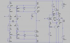
First off this is for fun and exchanging some ideas. I make no claim to inventing anything here it has all been somewhere before.
Classic op-amps input gm, Vas, and output buffer all end up relying on a linear input voltage to current stage (gm) feeding current to a high impedance node whose voltage is buffered to create a low output impedance. There are lots of embellishments around to increase the DC gain but the AC performance is usually limited by the linearity of the gm, the linearity of the gain node impedance (at AC frequencies the compensation capacitance plus any parasitics), and both the current needed to drive the output buffer and the voltage error across the output buffer. The last is problematic in that it (usually the crossover distortion) is differentiated before it can be expressed as an input current error, hence the rapid increase as frequency increases.
Before I go on I would like to say that a one size fits all op-amp is simply an unnecessary restriction. A simple enough signal path can give the user a couple of foolproof component substitutions that can optimize it for each application.
This being said I want to present a very ordinary signal path with a couple of additions to preserve simplicity and linearity. This circuit is not new but there are some differences to previous versions that I have seen (I don’t see everything posted). The signal path on the non-inverting side has been arranged more like a current mirror and on the other a folded cascade. The cascodes on the gain stage have their base current recaptured to keep the collector impedance very high and eliminate non-linear capacitive currents. The bootstrapped triple darling presents a very light load to the gain node and can be independently customized to easily drive low impedances. Though as I have previously stated there is no reason for every op-amp in your signal path to drive something like 50 Ohms.
The circuit here is just an outline and the devices are place holders but even with these fairly ordinary devices Aol is > 100k and more importantly the gain at 20K is 75dB. J1 and J2’s currents are set for bias and to set up the lower half of the input stage to also recapture the base current of the cascodes. Originally I had planned on a completely symmetric circuit with PFET’s. That is a fairly easy exercise for the reader.
I would like some suggestions for transistors, as far as I can tell I can get better than -100dB distortions at 20K, etc. with nothing more than this. As I said the degeneration resistors and comp cap would need to be changed for gain of one operation.
Attachments
Actually he wants a headphone amp. I have no idea why a headphone amp has to use opamps. I use in mine MOSFETs and BJTs in power supply, and SiC JFETs and vacuum tubes in the amp. It does not resemble any opamp. Well, it has balanced inputs, but it is transformer-balanced, no DC gain at all.
However, I have to admit, I am a zero in marketing...
Not really. The opamp apps today needs to drive more than just other amp/hardware inputs. -RNM
I think this particular one (LEDs in current sources) is Walt Jung's creation:
http://waltjung.org/PDFs/WTnT_Op_Amp_Audio_2.pdf
Yes, this is the usual method of bringing the opposing collectors of the input to the rail... Was Walt Jung first or?? But, the variation of bringing them to the output stage, between the emitter resistor and the output device is an improvement. Incremental. But incremental counts?
how is it different from IC?
can you tell us in which ways this is different from an IC packaged circuit? What parameters can be bettered with discrete (besides output current)? Thx RNM
First off this is for fun and exchanging some ideas. I make no claim to inventing anything here it has all been somewhere before.
Classic op-amps input gm, Vas, and output buffer all end up relying on a linear input voltage to current stage (gm) feeding current to a high impedance node whose voltage is buffered to create a low output impedance. There are lots of embellishments around to increase the DC gain but the AC performance is usually limited by the linearity of the gm, the linearity of the gain node impedance (at AC frequencies the compensation capacitance plus any parasitics), and both the current needed to drive the output buffer and the voltage error across the output buffer. The last is problematic in that it (usually the crossover distortion) is differentiated before it can be expressed as an input current error, hence the rapid increase as frequency increases.
Before I go on I would like to say that a one size fits all op-amp is simply an unnecessary restriction. A simple enough signal path can give the user a couple of foolproof component substitutions that can optimize it for each application.
This being said I want to present a very ordinary signal path with a couple of additions to preserve simplicity and linearity. This circuit is not new but there are some differences to previous versions that I have seen (I don’t see everything posted). The signal path on the non-inverting side has been arranged more like a current mirror and on the other a folded cascade. The cascodes on the gain stage have their base current recaptured to keep the collector impedance very high and eliminate non-linear capacitive currents. The bootstrapped triple darling presents a very light load to the gain node and can be independently customized to easily drive low impedances. Though as I have previously stated there is no reason for every op-amp in your signal path to drive something like 50 Ohms.
The circuit here is just an outline and the devices are place holders but even with these fairly ordinary devices Aol is > 100k and more importantly the gain at 20K is 75dB. J1 and J2’s currents are set for bias and to set up the lower half of the input stage to also recapture the base current of the cascodes. Originally I had planned on a completely symmetric circuit with PFET’s. That is a fairly easy exercise for the reader.
I would like some suggestions for transistors, as far as I can tell I can get better than -100dB distortions at 20K, etc. with nothing more than this. As I said the degeneration resistors and comp cap would need to be changed for gain of one operation.
can you tell us in which ways this is different from an IC packaged circuit? What parameters can be bettered with discrete (besides output current)? Thx RNM
Not really. The opamp apps today needs to drive more than just other amp/hardware inputs. -RNM
Not really. They don't need to be opamps, no matter what they drive.
I have to admit, I like Scott's exercise. Quite elegant.
Yes, this is the usual method of bringing the opposing collectors of the input to the rail... Was Walt Jung first or?? But, the variation of bringing them to the output stage, between the emitter resistor and the output device is an improvement. Incremental. But incremental counts?
He says right in the article that a version of it was first used in the LH0002 buffer, which I assume was a chip.
- Home
- Source & Line
- Analog Line Level
- Discrete Opamp Open Design