May be this is one of the potential distortion mechanisms you are addressing:
(P.364 from the excellent book of Bob Cordell: Designing Audio Power Amplifiers )
This may look exotic to me that I am an - non EE - amateur, but for a cautious designer, it should be a more homeland one.
Short time clipping certainly has the potential to occur in listening sessions quite frequently and get unnoticed.
The acoustic signature of clipping and subsequent sticking will be attributed to increased feedback from a person that adjusts the amount of feedback on an amplifier he is building/optimising and then evaluating by listening to music.
It is difficult to spot short term clipping while measuring, as the source material is rarely a music piece. The crest factor on some music is high and we may underestimate the overhead actually required.
Therefore, it is even more difficult to locate the stage that distorts first, then think of the underlying mechanism and decide on the remedy.
Regards
George
Indeed, and that is why a competent designer will take anti-saturation measures in his design, such as baker clamps, which, incidentally, are also used if not recommended by Bob C.
jan d
Or you could simply design an amplifier with a good clipping behaviour without using clamping.Indeed, and that is why a competent designer will take anti-saturation measures in his design, such as baker clamps, which, incidentally, are also used if not recommended by Bob C.
jan d
Sorry for beeing OT, but this is a power amp and not a discrete opamp.
BTW: THD at rated power (100W into 8 ohm, about 1 dB before clipping) is less than 0.5 ppm, (almost only 2nd and 3rd). Rock stable into 2 ohm complex load.
No exotic parts.
Cheers
Stein
Attachments
NFB vs. Overload/thd
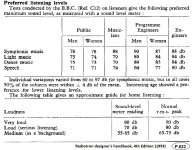
That is a good point to remember -- I tend to forget about it because I use high power amplifiers to prevent clipping and use high effeciency speakers. I suspect a lot more of clipping goes on than has been assumed; compressed recordings will bring us closer to the threshold of frequent clipping when played at moderate to high listening levels. And, low effecint speaker with low-moderate power amps will make it easier to clip, as well.
Amount of neg feedback, of course, affects the produced harmonic distortion structure when clipping does occure.... adding to the amps 'sound' character. The lack of this is often noticed in very high power amplifers.... say greater than 250W/cnl; Often described as an effortless and easy quality..... or just cleaner sounding. In fact, it may be one of the major reasons why amps are described as having a sound difference from one another.
Magazine reviewers and consumers swap in various amps and speakers during listening evaluations without regard to efficiencies and amp power rating differences but listening at same spl. -Thx RNM
May be this is one of the potential distortion mechanisms you are addressing: (P.364 from the excellent book of Bob Cordell: Designing Audio Power Amplifiers )
The acoustic signature of clipping and subsequent sticking will be attributed to increased feedback from a person that adjusts the amount of feedback on an amplifier he is building/optimising and then evaluating by listening to music.
Regards
George
That is a good point to remember -- I tend to forget about it because I use high power amplifiers to prevent clipping and use high effeciency speakers. I suspect a lot more of clipping goes on than has been assumed; compressed recordings will bring us closer to the threshold of frequent clipping when played at moderate to high listening levels. And, low effecint speaker with low-moderate power amps will make it easier to clip, as well.
Amount of neg feedback, of course, affects the produced harmonic distortion structure when clipping does occure.... adding to the amps 'sound' character. The lack of this is often noticed in very high power amplifers.... say greater than 250W/cnl; Often described as an effortless and easy quality..... or just cleaner sounding. In fact, it may be one of the major reasons why amps are described as having a sound difference from one another.
Magazine reviewers and consumers swap in various amps and speakers during listening evaluations without regard to efficiencies and amp power rating differences but listening at same spl. -Thx RNM
It seems so far off from the OP requirements for this thread to be speaking about distortion in power amplifiers here. But at the same time we have to look at the paradigm that the current marketing has created in consumer audio. Ever smaller speakers and enclosures with low power multichannel amplifiers running on a single power supply and expected to drive a sub-woofer. Now the consumer thinks that they can turn up the system and listen at any type of realistic level and what do we have, pure mud. That is so far from what we as a DIY group are expecting and designing for. But we also have to look at the differences of a horn loaded high efficiency system vs. a low efficiency direct radiator system with wide bandwidth devices. The power requirements are different by a exponential rate between these two opposing camps. One may be fine with a small high quality amplifier and the other will need a high current high power amplifier with much more headroom to handle those compressed bass passages that are being reproduced. So the actual needs are quite different between the two camps.
Now back to your discrete opamp design.
Now back to your discrete opamp design.
My copy arrived yesterday, and there is a lot of good stuff within.Speaking of Bob, he has a no feedback pre-amp in Linear Audio Vol. 4. A JFET diff-pair (gm) feeding a cascoded high gain stage, with an open-loop unity gain buffer. That would be an interesting variant, internal feedback, or no feedback at all, or maybe even a combo.
One thing I noticed about Bob's non-global-feedback MM preamp: it assumes the cartridge is connected differentially*. This I suspect in large part accounts for the reasonable distortion numbers, as even harmonics will nearly cancel. The MC preamp is single-ended except for a quasi-differential common sense, despite using groups of differential pairs. But of course for almost all MC cartridges, the voltages will be much lower.
I could go on about other aspects of that article, as well as a lot of the other articles, but it would get hopelessly off-topic.
Brad
*for most existing equipment this will require rewiring the tonearm with shielded twisted-pairs. I can hear KOJ saying "the way they OUGHT to be"
 Keith also had his preamp in the base of his AR turntable "where it belongs!"
Speaking of Bob, he has a no feedback pre-amp in Linear Audio Vol. 4. A JFET diff-pair (gm) feeding a cascoded high gain stage, with an open-loop unity gain buffer. That would be an interesting variant, internal feedback, or no feedback at all, or maybe even a combo.
I still like the use of the exact same circuit and its power supply and only varying the OL gain to vary fb amount and to do so as you listen. Can you hear a difference? -RNm
George, this was also covered thoroughly in "Valve Amplifiers."
You mean Morgan Jones book. Yes, and on some others as well, less thoroughly maybe, down to the old Radiotron designer's handbook.
But my point was to trickle Mr. Curl for his use of the “more exotic” term.

I certainly do not qualify to make a statement but I am confident that “exotic” is as far as it should go for an expression as to any form of distortion. Beyond that, is the magician’s land.
It is more than that, George
It has to be, I agree.
I don't anticipate clipping of any kind in most of my designs, without having the police called for too much noise.
Mr. Curl, I am not addressing your designs. But too much noise is the result of average SPL. You know that you can have the cop at your door with your amplifier outputing on average anything between 2 and 20 Watts depending on your speakers sensitivity. What about some short excursions 12-16db higher?
See RNMarsh here
That is a good point to remember …
Indeed…..if not recommended by Bob C.
jan d
The beauty of this work for me Jan is that, all the myriad small but important details in the design of an amp are rationally presented and adequately explained.
Here I would like to make a question which I think is relevant to the subject of this thread.
Which of all the potential technical-design- issues met on a power amplifier are not to be faced in the design of this discrete op. Amp (assuming appropriate scaling of power) ?
George
Attachments
Last edited:
...went on with simulation of the symmetrized LinuxguruBuffer.
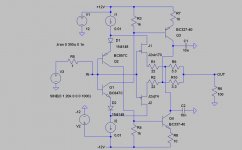
The attached schematic is showing some additional resistors to allow proper biasing.
Overall the simulated performance is among the better ones I saw in simulation so far and worth a real life trial (..my LTSpice never pleases me with -120db THD...)
But I have to state again, I do not trust the absolute values of the simulation of harmonics in the sub -80db range.
In fact the choice of Q3 and Q4 is not my favorite (heat handling and linearity of Ic/Uce characteristic), but was available in LTSpice.
In reality I would propose 2SA1930 and 2SC5170.
Q3 and Q4 are biased around 30mA.
The schematic shows degeneration resistors for Q3 and Q4.
They are not necessary for biasing, but I would guess that reality performs better in THD and TIM with them, while simulation does not show much effect (up to now only single tone simulated).
To my understanding Q3 and Q4 cannot be rated as inactive support functions, they are actively handling music signal in a similar way we are used
to it from Sziklai darlingtons. And we get the same sort of oscillations that need taming, which I did with a brute force dominant pole - not really nice, but acceptable as a starting point.
Furtheron in reality it might be better to use red LEDs for D1 and D2.
Last but not least the buffer is showing a strong increase of distortion when driven from high impedances, similar as it is known from diamond buffers.
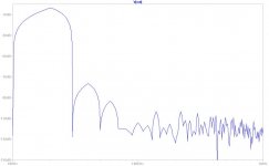
The attached pictures show
- Schematic
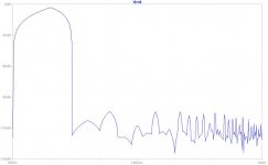
- Harmonics at 20kHz/1V into 100 Ohms (R6)
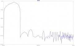
- Harmonics at 20kHz/1V into 33 Ohms (R6)
- Harmonics at 20kHz/1V into 33 Ohms (R6), but 100k driving impedance (R5)
The attached schematic is showing some additional resistors to allow proper biasing.
Overall the simulated performance is among the better ones I saw in simulation so far and worth a real life trial (..my LTSpice never pleases me with -120db THD...)
But I have to state again, I do not trust the absolute values of the simulation of harmonics in the sub -80db range.
In fact the choice of Q3 and Q4 is not my favorite (heat handling and linearity of Ic/Uce characteristic), but was available in LTSpice.
In reality I would propose 2SA1930 and 2SC5170.
Q3 and Q4 are biased around 30mA.
The schematic shows degeneration resistors for Q3 and Q4.
They are not necessary for biasing, but I would guess that reality performs better in THD and TIM with them, while simulation does not show much effect (up to now only single tone simulated).
To my understanding Q3 and Q4 cannot be rated as inactive support functions, they are actively handling music signal in a similar way we are used
to it from Sziklai darlingtons. And we get the same sort of oscillations that need taming, which I did with a brute force dominant pole - not really nice, but acceptable as a starting point.
Furtheron in reality it might be better to use red LEDs for D1 and D2.
Last but not least the buffer is showing a strong increase of distortion when driven from high impedances, similar as it is known from diamond buffers.
The attached pictures show
- Schematic
- Harmonics at 20kHz/1V into 100 Ohms (R6)
- Harmonics at 20kHz/1V into 33 Ohms (R6)
- Harmonics at 20kHz/1V into 33 Ohms (R6), but 100k driving impedance (R5)
Attachments
I agree, nothing really wrong with a string of 1N4148.
It is more my taste to use red LEDs, because of less component count and red LEDs are hard to beat in terms of noise (not much of relevance here, agreed..).
From my understanding the influence of the drive impedance is caused by the fact that Q1 and Q2 do operate on mostly constant Ic, but not perfectly constant. You will find the modulated base currents of Q3 and Q4 there (similar as in a diamond buffer). This then translates into modulation of the input current of the buffer - reflecting the non linearities of the current gain of all the BJTs. BJTs show these non linearities also at low frequencies and DC. I would assume that a filter may shape the frequency dependency of these distortions, but I am wondering how a filter should cure it.
Nevertheless, I a curious to your real life findings - in case you decide to go for experiments.
...went on with simulation of the symmetrized Linuxguru Buffer.
I may start a new thread for in-depth explorations of linuxguru's approach. It deserves some elaboration and further development, I think, and I'd also like to make things public to prevent someone from patenting them.
I have a good many variants already, while loosely justifying the time spent because of the circuit's applicability to many things. Although it can be incorporated into global loops, I'm seeing such good performance of modified versions that it's tempting to let them stand alone, with possibly a d.c. servo in some offset-sensitive cases.
It's interesting how close the circuit is to merely a complementary feedback pair. But not quite.
- Home
- Source & Line
- Analog Line Level
- Discrete Opamp Open Design