Number two (from post 68) is not too bad. Whose is it? It looks like something that really works.
What?!?! you didn't see the "Je-990" on that one? I assume you mean this one in the middle?
Attachments
Sorry guys EVUL started this so fast I was caught off guard. I hope to put up a couple of ideas later today. I don't think complexity is a goal in itself, performance is. I also don't think a design contest with an 8 transistor limit should be a prime goal.
OK, so re-write the rules then....
What IS the goal? So far, it's been talking about this transistor vs. this other one and whether or not it's still produced.

I actually don't like the differential opamp topology anyway. I don't use it (when I play around in my spice simulator) except for power amps.
What?!?! you didn't see the "Je-990" on that one? I assume you mean this one in the middle?
My bad. The one in the middle from post 70, with the dual JFET front end. I like that one.
My bad. The one in the middle from post 70, with the dual JFET front end. I like that one.
You'll have to ask ThorstenL about that one.
http://www.diyaudio.com/forums/anal...urls-blowtorch-preamplifier-part-ii-1886.html
All I got so far is that it is very old. (1973?)
I was just posting random schematics to get the creative juices going here. I don't mean to endorse one over another one. I'm not really knowledgeable enough to know which would be better than another anyway.
Last edited:
I hope he can be persuaded to return someday. However, this seems to be the season for leaving sites (I recently left a couple of "social" ones, no doubt pleasing some and disappointing others).You'll have to ask ThorstenL about that one.
JE990
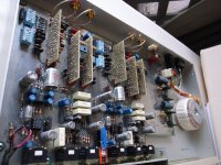
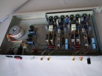
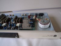
One of the 990's best characteristics was it's stability into (relatively) difficult loads. It was designed by Deane (RIP) to drive his transformers (albeit he recommended output isolators) so it had to be stable. The 990 was quiet enough to make a high-end MM RIAA preamp in 1988, as executed in the PR&E (Pacific Recorders & Engineering) TX990, still a great-performing pre (see attached pix)
Howie
Howard Hoyt
CE - WXYC-FM 89.3
UNC Chapel Hill, NC
www.wxyc.org
1st on the internet
As a footnote, I worked tangentially with Bill Whitlock (now Jensen Pres) at Capitol Records when they decided to ditch their own digital duplication bin and install our DAAD system. He is one of the brightest engineers I have ever worked with. He came from Quad-8 (as did Deane) interestingly enough, since a Quad-8 amp schematic has just been posted...
Anything less complex than a Jensen 990 is a joke, and not worthy of consideration. We are looking for EXCELLENT circuits that we would use in the best audio equipment available today.
One of the 990's best characteristics was it's stability into (relatively) difficult loads. It was designed by Deane (RIP) to drive his transformers (albeit he recommended output isolators) so it had to be stable. The 990 was quiet enough to make a high-end MM RIAA preamp in 1988, as executed in the PR&E (Pacific Recorders & Engineering) TX990, still a great-performing pre (see attached pix)
Howie
Howard Hoyt
CE - WXYC-FM 89.3
UNC Chapel Hill, NC
www.wxyc.org
1st on the internet
As a footnote, I worked tangentially with Bill Whitlock (now Jensen Pres) at Capitol Records when they decided to ditch their own digital duplication bin and install our DAAD system. He is one of the brightest engineers I have ever worked with. He came from Quad-8 (as did Deane) interestingly enough, since a Quad-8 amp schematic has just been posted...
Attachments

Seems like this can be a real fun and entertaining excersize if just not taken too seriously.
Is there any consideration to try and exploit any potential advantages of "newer" available discrete components, which I can only think of the small signal mosfets (Siliconix-Vishay..). Mixing the best characteristics of FETS/BJT/MOSFETs also has some appeal for discrete.
Thanks
-Antonio
Is there any consideration to try and exploit any potential advantages of "newer" available discrete components, which I can only think of the small signal mosfets (Siliconix-Vishay..). Mixing the best characteristics of FETS/BJT/MOSFETs also has some appeal for discrete.
Thanks
-Antonio
Is there any consideration to try and exploit any potential advantages of "newer" available discrete components, which I can only think of the small signal mosfets (Siliconix-Vishay..).
-Antonio
For example?
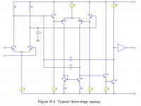
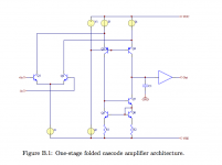
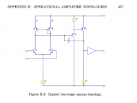
Samuel Groner has shown the most popular topologies for Opamps.
....but did not include in his analysis important one that's been around for ages as discrete design.
Attachments
Seems like this can be a real fun and entertaining excersize if just not taken too seriously.
Is there any consideration to try and exploit any potential advantages of "newer" available discrete components, which I can only think of the small signal mosfets (Siliconix-Vishay..). Mixing the best characteristics of FETS/BJT/MOSFETs also has some appeal for discrete.
Thanks
-Antonio
That would be good to know and learn thier potential.
Past standard circuit
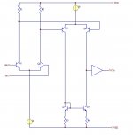
I used that topology for a passively equalized phono stage (with fet input) - TAA 3/80. Good basic circuit.
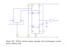
....but did not include in his analysis important one that's been around for ages as discrete design.
I used that topology for a passively equalized phono stage (with fet input) - TAA 3/80. Good basic circuit.
....but did not include in his analysis important one that's been around for ages as discrete design.
That's (post 94 schematic) also close to what Rich May did as power amplifiers in the Harman/Kardon TC400, although he inserted a common-base stage in the one second stage collector to equalize the dissipations of the second diff pair. He also compensated with a series RC network across the input collectors, and had some emitter degen in both diff pairs iirc. The resulting design had o.k. static distortion performance, and very good and symmetrical slew rate. The output buffer was I think cascaded common-collectors with the fast Toshiba output devices (2SA1302? etc).
I think I inherited it and screwed it up a bit
 This was in the early days. The line of automotive amps didn't sell very well; they were too expensive, and because of the "transverse tunnel cooling" didn't have the large expanse of heatsink beloved of the kids.
For example?
Along the lines of SI1029X and or subsequentially larger devices (problem is even when I was using these a few years ago the parts wer becoming obsolete so quick, but at least they were being replaced with newer part numbers).
So I dont know what is readily available today but there seems to be a number of mfgr's and series to speculate from.
Hope this helps
-Tony
Thanks, didn't know of those. Most of the work in such parts is for rather lower voltage ones.
diamond buffer possibility
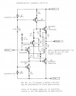
Since virtually all of the likely designs to pour forth are going to want an output buffer, I dredged up and dusted off the attached.
It can be scaled back to lower rails without too much trouble. The bandwidth per se from a 1k source R is about 35MHz. There is the advantage of reduced thermal distortion when used with about a 515 ohm load, since the output devices are equidissipational*, that is, their dissipations roughly track. But when, as we anticipate, this is inside of an overall global loop with plenty of loop gain, the rest of the works will easily correct for dissipation-induced shifts, as the shifts should be fairly slow, and thus the thermal concerns should be minor.
The bootstrapping of the input devices raises the input Z, but also requires some lumped C to reduce peaking. Since such C is constant, the distortion at high frequencies at the input is reduced.
Short-circuit protection is left as the proverbial exercise to the reader.
Brad
*the approximate condition for this is that the peak output current into the load at just before onset of clipping is twice the quiescent current. Things are slightly more complicated by the emitter ballasting and the fact that the input devices draw their operating current from the output devices due to the bootstrap arrangement.
Attachments
- Home
- Source & Line
- Analog Line Level
- Discrete Opamp Open Design