JFET's have two temperature coefficients the Idss and the Vp are opposite in sign so there is a point of zero TC.
Thanks Scott. Yes, precisely. I suppose I wouldn't violate the fair use doctrine too much to copy the entire short section of Cobbold, as I believe it is long out of print.
Thanks Scott. Yes, precisely. I suppose I wouldn't violate the fair use doctrine too much to copy the entire short section of Cobbold, as I believe it is long out of print.
My copy walked years ago, Abebooks has it off and on for $70 or so.
My copy walked years ago, Abebooks has it off and on for $70 or so.
I just checked. Yes, OOP for sure. However:
BookFinder.com: Search for New & Used Books, Textbooks, Out-of-Print and Rare Books, which searches most of the sites (sometimes misses recent Amazon offerings though), has some a lot cheaper, probably ex-library even when they don't say that explicitly. That's my go-to for comparables on books, particularly when I find I have duplicate copies.
I love to look at the front free endpaper on books of that age, when I still used to write my name there. You can actually make out the spelling, easily. Not anymore

As good a reason as any.
They also allowed for as few transistors as possible (no need for additional current sources for bjt biasing). It works very well --- if you find the matches as suggested; I got about 15-20% matches (.8v/1K) out of a batch of the jFETs.
close enough?
.8v is about it but what I get from the circuit works extreamly well.... maybe could be even better... but was not needed. Maybe the data spec sheet is a little different from the devices I have... who knows. I didnt pursue it further when the prototype was as stable as it is. Thx-RNM
Sorry Dick I misread the schematic (I read 51.1 Ohms on the penciled in values), you were aiming at 800uA but does not look too close.
.8v is about it but what I get from the circuit works extreamly well.... maybe could be even better... but was not needed. Maybe the data spec sheet is a little different from the devices I have... who knows. I didnt pursue it further when the prototype was as stable as it is. Thx-RNM
Last edited:
.8v is about it but what I get from the circuit works extreamly well.... maybe could be even better... but was not needed. Maybe the data spec sheet is a little different from the devices I have... who knows. I didnt pursue it further when the prototype was as stable as it is. Thx-RNM
Right, nothing gained by belaboring these details.
.8v is about it but what I get from the circuit works extreamly well.... maybe could be even better... but was not needed. Maybe the data spec sheet is a little different from the devices I have... who knows. I didnt pursue it further when the prototype was as stable as it is. Thx-RNM
An added final clarification: Note also that even though the matching uses .8 mA. With the values used in circuit (Re = 650 instead of 1K), the actual Id measures 1.1-1.2mA. Which is right where it needs to be for low TC.
-RNM
Last edited:
I just checked. Yes, OOP for sure. However:
BookFinder.com: Search for New & Used Books, Textbooks, Out-of-Print and Rare Books, which searches most of the sites (sometimes misses recent Amazon offerings though), has some a lot cheaper, probably ex-library even when they don't say that explicitly. That's my go-to for comparables on books, particularly when I find I have duplicate copies.
I love to look at the front free endpaper on books of that age, when I still used to write my name there. You can actually make out the spelling, easily. Not anymore
Ironic that this returned Abebooks as the lowest available ~$11, in any case certainly worth replacement at that price.
An added final clarification: Note also that even though the matching uses .8 mA. With the values used in circuit (Re = 650 instead of 1K), the actual Id measures 1.1-1.2mA. Which is right where it needs to be for low TC.
-RNM
Dick. you could use an avatar and nice pithy signature.
Ironic that this returned Abebooks as the lowest available ~$11, in any case certainly worth replacement at that price.
Yes, despite the improvements in parts since 1970, it holds up well.
several on Amazon today... reasonable, various conditions... got one myself, should be the right thickness to hold up the back of my laptop, I expect...
_-_-bear
lessee, everything I want to know about a type of device I can barely get a hold of now, and surely will not be able to get shortly?
_-_-bear
lessee, everything I want to know about a type of device I can barely get a hold of now, and surely will not be able to get shortly?
Been meaning to mention this before I forget to open my mouth... I really liked this opamp for a long time, it seemed to do well when other opamps got a bit "unhappy", it was mentioned to me by an AD person that the "secret" was in the ability of the front end to handle, ummm... what did he say?... I think it was large differential signals, not sure.
http://www.analog.com/static/imported-files/data_sheets/AD845.pdf
_-_-bear
http://www.analog.com/static/imported-files/data_sheets/AD845.pdf
_-_-bear
Dick. you could use an avatar and nice pithy signature.
Suggestions?
[I think i pithed my pants]
Before we get too confused about a lot of things, let's put things in order.
First, if you have an active load, you should try to reduce the intrinsic (noise) gain of the load by reducing Gm through any means available, usually a series R.
You have to look at the whole input device assortment to determine how much FORWARD gain you will have. It is NOT the NOMINAL voltage gain, but the effective Gm(R[load]) where R[load] will be a very high and almost undefined impedance.
So since both the active load and the input see R[load] then the only thing you have to compare is their intrinsic voltage gain, each one, and the self noise of the active parts.
The 'trick' is to lower the Gm of the active load, to be lower than the effective forward Gm, in each leg, of the source.
This is NOT as easy as it might look.
To intuit the process, think about a SUMMING amplifier, where you have 2 separate active sources contributing. IF you do not use enough emitter or source resistor degeneration, you WILL not achieve what the input stage, itself, is capable of.
John, a good post.
Cheers
Stein
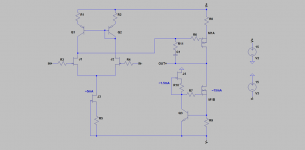
How about a simple circuit with an SE output stage...
Designed to use the 2SK2145 in the front end and medium power switching complementary mosfets in a single package for the second stage. Works well without a VAS, +/-8 to +/-18v supplies, will drive to within 3 volts of the rails, +/-8 volts into 600 ohms, and makes for a small circuit layout using surface mount.
I'm happy to post part numbers and values for those who care but am interested in comments on the topology first.
Dave
Attachments
Last edited:
parallel Not series -
First to point out that the push-pull input stage has the jFETs effectively in parallel. The classic differential stage puts the two transistors in series. Thus the noise potential is lower in push-pull than the other (all things being equal).
If you select the jFETs I used and show, you wont have to worry about the issue of finding good compliments and thier TC bias etal.... I did the leg work for you. It isnt luck to get the zero TC from the circuit.
The circuit I used gets as low thd into 30 Ohms as a high neg feedback design but does so with only 8 transistors.
Their total cost is below a single BF862 diff pair. It will be hard to beat in low to moderate gain applications for performance, cost, simplicity. One would have to be cheaper and better performance for audio and use fewer parts to qualify as all around "better". It sounds great, BTW. -Dick Marsh
The other problem here is that the complementary series connection ideally has both JFETs operating close to their zero tempco points. But it's work just to find that point for a single FET. When we need to do it for two of them AND have that operating point be the same magnitude, the selection task is daunting. Separate current generators could be provided I suppose, and the signals combined afterwards. But despite the appeal of a push-pull stage, a single-ended one has a lot going for it, particularly as good NFET duals still exist (and can be configured successfully as low-drift single-ended stages, or of course as conventional differential pair front ends).
If we get lucky and the two track, that's another way that the phenomena can be saved. We still have high noise to deal with for the few currently-manufactured devices. With modest gains needed for some applications, perhaps the noise upstream will dominate, and of course the lower gains reduce the voltage drift concerns as well.
First to point out that the push-pull input stage has the jFETs effectively in parallel. The classic differential stage puts the two transistors in series. Thus the noise potential is lower in push-pull than the other (all things being equal).
If you select the jFETs I used and show, you wont have to worry about the issue of finding good compliments and thier TC bias etal.... I did the leg work for you. It isnt luck to get the zero TC from the circuit.
The circuit I used gets as low thd into 30 Ohms as a high neg feedback design but does so with only 8 transistors.
Their total cost is below a single BF862 diff pair. It will be hard to beat in low to moderate gain applications for performance, cost, simplicity. One would have to be cheaper and better performance for audio and use fewer parts to qualify as all around "better". It sounds great, BTW. -Dick Marsh
Last edited:
First to point out that the push-pull input stage has the jFETs effectively in parallel. The classic differential stage puts the two transistors in series. Thus the noise potential is lower in push-pull than the other (all things being equal).
If you select the jFETs I used and show, you wont have to worry about the issue of finding good compliments and thier TC bias etal.... I did the leg work for you. It isnt luck to get the zero TC from the circuit.
The circuit I used gets as low thd into 30 Ohms as a high neg feedback design but does so with only 8 transistors.
Their total cost is below a single BF862 diff pair. It will be hard to beat in low to moderate gain applications for performance, cost, simplicity. One would have to be cheaper and better performance for audio and use fewer parts to qualify as all around "better". It sounds great, BTW. -Dick Marsh
How many of these did you build? Are you aware of the huge spread of values for the pertinent parameters of the 5457 and 5460? Would you be prepared, based on your experience, to go into production of, say, 10k pieces? That's usually my world.
The BOM is below the cost of a single BF862 pair? I buy 862s for 22 cents in 100's from Mouser, iirc, and I don't think they are doing me any special favors. Perhaps you had an old Toshiba dual in mind? Even they didn't used to be all that expensive when they were still in production, but yes, as Wurcer remarked, even the single SK170 has a die size bigger than some ADI entire video amps
Even with 100% yield from a wafer you won't be getting all that many from a run.I have nothing against the topology per se. However, the requirements on voltage drift are modest for a closed loop gain of 4.3. As well, you provide a trim adjustment for initial offset, and although useful, you thereby add a potential concern for manufacturing and reliability.
The noise remark (parallel versus series) is certainly true. However, to operate the devices at the zero tempco point requires substantial resistance in series with each source. If these were 2SK170V and 2SJ74V (the latter getting very scarce now), there's the chance that the zero tempco point would occur around Idss, and that would be fat city indeed. However, for both of the devices from process 55 and 89, zero tempco occurs far from Idss, at operating points that correspond to low transconductance and relatively high noise, even before considering the thermal noise of the series resistances.
Will such noise really be a problem? Quite possibly not, depending on the noise in the source.
Again, nothing against the topology. With a couple of better parts it could be very low noise and likely still lower distortion, higher bandwidth. I don't doubt that it sounds good.
1. How many of these did you build? Are you aware of the huge spread of values for the pertinent parameters of the 5457 and 5460? Would you be prepared, based on your experience, to go into production of, say, 10k pieces? That's usually my world.
2. The BOM is below the cost of a single BF862 pair? I buy 862s for 22 cents in 100's from Mouser, iirc, I have nothing against the topology per se. However, the requirements on voltage drift are modest for a closed loop gain of 4.3.
3. As well, you provide a trim adjustment for initial offset, and although useful, you thereby add a potential concern for manufacturing and reliability.
4. The noise remark (parallel versus series) is certainly true. If these were 2SK170V and 2SJ74V (the latter getting very scarce now), there's the chance that the zero tempco point would occur around Idss, and that would be fat city indeed.
5. However, for both of the devices from process 55 and 89, zero tempco occurs far from Idss, at operating points that correspond to low transconductance and relatively high noise, even before considering the thermal noise of the series resistances.
6. Will such noise really be a problem? Quite possibly not, depending on the noise in the source.
7. Again, nothing against the topology. With a couple of better parts it could be very low noise and likely still lower distortion, higher bandwidth. I don't doubt that it sounds good.
1. If I were building in high volume, i would have the devices sorted/graded at the factory. And, with cheap labor used, the final batch can be quickly determined. This would be true with any complimentary jFET used.
2. 22 cents is good. One builder reported finding the ones I use for 3 cents. 1/7th the cost.
3. Trim isnt needed if matched. But could also be fixed values... even if selected. Of course, you know that already.
4, 5. Other devices have been used/tried as I have mentioned before. In addition, paralleling jFETs could be done with minor R changes.
6. Noise is definately not an issue for appl at line levels.
7. My own Goal: Low parts count - no more than 8 transistors, super high performance (H2-3 below -100db re 1v AT 30 Ohms), high drive capability into low Z, no DC servo and be low cost. Then throw in that it must do this withOut high gnfb and the open loop bandwidth must be 40Khz ( I missed that mark a little) for the audiophiles. That was my goal and challenge to others. Doing "better" with more cost and complexity just didnt seem like a proper challenge to me.
Have a nice day. Got to go do some reading, now. -Dick Marsh
Last edited:
- Home
- Source & Line
- Analog Line Level
- Discrete Opamp Open Design