I do not.How do you calculate the skin effect in a feedback resistor?
Last edited:
because he can hear the skin effectWHY?

Skin effect depends on frequency, resistivity and permeability of the material, the formula is not so hard to find!
Any material that has seriously more resistivity than a metal shows skin-depths at audio frequencies measured in metres, its not something you worry about.
And with copper its measured in miilimetres, so metal-film resistors aren't a problem either as they are thin-film, much less than mm
Any material that has seriously more resistivity than a metal shows skin-depths at audio frequencies measured in metres, its not something you worry about.
And with copper its measured in miilimetres, so metal-film resistors aren't a problem either as they are thin-film, much less than mm
Let's compare skin effect with Miller capacitance.Still did not get it?
The MOSFETS and tubes are better in sounds because they are voltage-controlled. This means there is no uncontrollable skin-effect on their input (grid, gate), because the AC current is very low.
This doesn't make sense, as all your idle chats about skin effect.Originally Posted by Alex Ra
Still did not get it?
The MOSFETS and tubes are better in sounds because they are voltage-controlled. This means there is no uncontrollable skin-effect on their input (grid, gate), because the AC current is very low.
Hello Scott
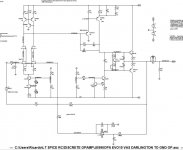
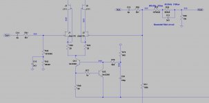
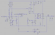
I need a simple discrete opamp that I can build with parts available in my stock and found your jfet ips based on the 990.
After some work I came up with the following design that sims ok. I am now ready to start board layout but would really appreciate your comments on the solutions I found.
Some differences exist:
The VAS buffer has it's collector to GND instead of to the negative rail so I have less power to dissipate there.
I used a cascoded CCS on the LTP tail based on a design by Bob Cordell.
Instead of diodes to act as voltage spreader I use one NPN but I am not sure about the best resistor values to use in the spreader.
I have one DC Servo implemented with a jfet opamp wired as a non inverting integrator.... does it impair stability ?
Thank you in advance for your help.
Best
Ricardo
Attachments
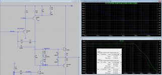
You should probably have a cap across the feedback resistor. The purpose of this cap is to supply the gate capacitance of J2 which otherwise will cause peaking and reduce phase margin. J1 also might need a cap... Generally you have a ~100pF cap to ground at the input transistor so that source impedance doesn't affect gain at RF.
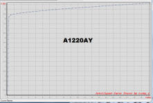
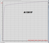
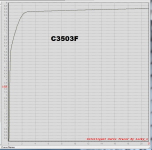
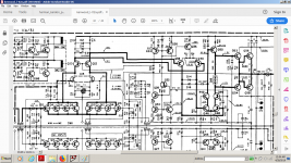
I've decided to use a different set of TO-126 transistors for the output stage of my DOA; it's definitely not a JE990 clone, not even close. I've chosen the KSC2690A/KSA1220A pair.
Here are the I-V curves in the vicinity of 8mA, which I measured a couple years ago.
_
Here are the I-V curves in the vicinity of 8mA, which I measured a couple years ago.
_
Attachments
You should probably have a cap across the feedback resistor. The purpose of this cap is to supply the gate capacitance of J2 which otherwise will cause peaking and reduce phase margin. J1 also might need a cap... Generally you have a ~100pF cap to ground at the input transistor so that source impedance doesn't affect gain at RF.
Hi Kean
The feedback circuit I posted was used only for simulation purposes.
In reality I will use this opamp in the second stage of a RIAA phono.
The feedback will create the 318us and 3180us sections of the RIAA curve.
In the first stage I will take care of the 75us (treble cut).
Attachments
Please comment...
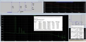
q20, q22, q28, q30, q31, q42, q46, q44, q48 are 2sc1845 in my attachment
i kinda doubt that ksc1845 is linear enough biased only by a red LED, nor it's temp compensated in any way.This is the only truth i know about ksc1845 lowest noise and stable operation used in the highest quality phono preamp circuit ever designed in an audio equipment:
Attachments
Last edited:
- Home
- Source & Line
- Analog Line Level
- Discrete Opamp Open Design