An often referred to amplifier circuit put up on the forum by Bob Cordell, with excellent theoretical performance, loses orders of magnitude accuracy when attached to something like real world parts. Plus, when the circuit is pushed a bit in terms of current delivery, slewing, etc, it again is easy to identify areas in the circuit where misbehaviour starts to rear its ugly head - and this is with relatively 'perfect' components ...
Separate CCS biasing hasn't shown any difference in simulation so I decided to keep it simple.
I did some preliminary simulations with the LTP BJTs replaced by cascoded JFETs running at about 1 mA with about 47R degeneration each, separate CCSes for the LTP and VAS, VAS quiescent current of 2 mA. C4, C5 = 68pF, R7=22R (smaller than shown in your BJT variant). I omitted the capacitance multiplier and some bypasses for the sim.
It does perform rather well - as good or better than most of the FET990 variants seen earlier in this thread. Simulated GBW runs to about 20 MHz.
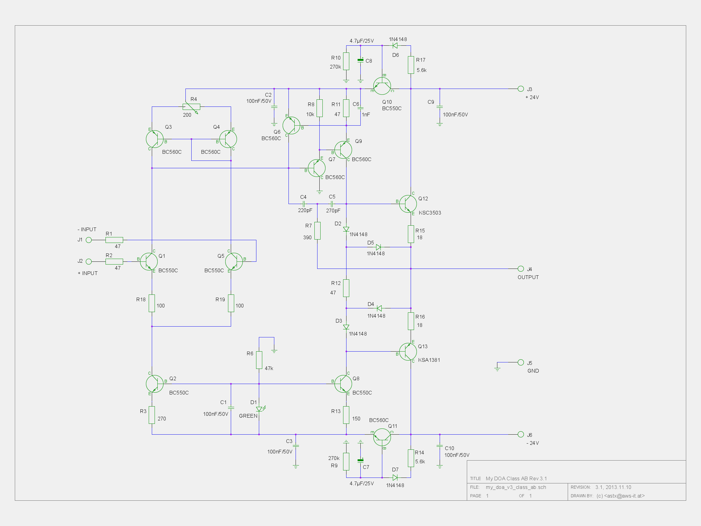
The only thing I don't understand is the function of Q6, BC560c. In normal operation, it seems to be at cut-off. It can only conduct (and clamp) when the VAS current reaches about 12 mA continuous, which probably can't ever happen in normal operation (might happen when the output is shorted). I also noticed that the Baker clamp diode(s) on the VAS, which are typically found in Blameless/JE990 variants, are missing.
The only thing I don't understand is the function of Q6, BC560c. In normal operation, it seems to be at cut-off. It can only conduct (and clamp) when the VAS current reaches about 12 mA continuous, which probably can't ever happen in normal operation (might happen when the output is shorted).
Yes, otherwise positive short circuit current will be 24-0.7-0.7/47=0.45A
got a reference, article, posted measurements?
An often referred to amplifier circuit put up on the forum by Bob Cordell, with excellent theoretical performance, loses orders of magnitude accuracy when attached to something like real world parts. Plus, when the circuit is pushed a bit in terms of current delivery, slewing, etc, it again is easy to identify areas in the circuit where misbehaviour starts to rear its ugly head - and this is with relatively 'perfect' components ...
SOA protection of VAS for the positive side half wave. The negative half wave is protected very good by CCS....
The only thing I don't understand is the function of Q6, BC560c. In normal operation, it seems to be at cut-off.
...
BR, Toni
Could you post a pic of your mod? Or better still the *.ASC file.
As you've 'improved' it, it is your copyright .. though I'm sure Doug won't mind even if you posted his original pic. as its for education.
My experiences with the Schlotzaur's circuit with 2, 3 and 4 transistors current mirrors are shown here, the text is in french but numbers and figures are self-explaining :
Distorsions peu connues des étages d'entrée des amplis
Distorsions peu connues des étages d'entrée des amplis
vendredi 22 avril 2011 19:17:56
See the whole thread for more details.
My main aim was to verify the existence of thermal distortion in input stages.
My own reference for a buffer using a differential input stage and an emitter follower only is shown below and dates back 1987
( L'tage d'entre de l'ampli -3- diffrentiels insolites (Hphastos) ) :

I have thought to test such circuits for a long time and reading the good numbers of D. Self's related chapter prompts me to do it. That was in 2011.
Below, ASTX's DOA ( http://www.diyaudio.com/forums/anal...screte-opamp-open-design-153.html#post4008491 ) :
Not often seen : C6, 1 nF.
What about a complete by-pass of VAS emitter resistor R11 / 47 Ohm by an electrolytic cap ?
Not often seen : C6, 1 nF.
What about a complete by-pass of VAS emitter resistor R11 / 47 Ohm by an electrolytic cap ?
C6 increases gain/phase margin.Below, ASTX's DOA ( http://www.diyaudio.com/forums/anal...screte-opamp-open-design-153.html#post4008491 ) :
Not often seen : C6, 1 nF.
What about a complete by-pass of VAS emitter resistor R11 / 47 Ohm by an electrolytic cap ?
...
I've used smaller values (~47 pF) at C6 in my FET990. It doesn't seem to hurt to go with 1 nF in the simulation. That capacitor should preferably be linear, so it's probably best to stick with C0G or PPS (both available in 0805, maybe smaller, for SMD implementations).
Also noticed that the Cherry compensation caps are 2x-4x larger than what I use in the FET990, which is in the region of 47..100 pF.
Also noticed that the Cherry compensation caps are 2x-4x larger than what I use in the FET990, which is in the region of 47..100 pF.
...
Also noticed that the Cherry compensation caps are 2x-4x larger than what I use in the FET990, which is in the region of 47..100 pF.
Cherry compensation? Thought I've used TMC (D. Self would call it "output inclusive") compensation...
Of course I have used C0G type capacitors for C4, C5 and C6.
Last edited:
Cherry compensation? Thought I've used TMC (D. Self would call it "output inclusive") compensation...
I might have confused the nomenclature, but it seems similar in principle to the topology shown in this posting by Edmond Stuart:
http://www.diyaudio.com/forums/soli...terview-negative-feedback-50.html#post1160022
TMC, Output-Inclusive, Cherry - seem vaguely related.
Of course I have used C0G type capacitors for C4, C5 and C6.
Sorry, I was responding to another poster who suggested using an electrolytic for C6, which I think is a bad idea.
Thanks for these links but what does Schlotzaur actually refer to?My experiences with the Schlotzaur's circuit with 2, 3 and 4 transistors current mirrors are shown here, the text is in french but numbers and figures are self-explaining :
Distorsions peu connues des étages d'entrée des amplis
Distorsions peu connues des étages d'entrée des amplis
vendredi 22 avril 2011 19:17:56
...
My own reference for a buffer using a differential input stage and an emitter follower only is shown below and dates back 1987
( L'tage d'entre de l'ampli -3- diffrentiels insolites (Hphastos) ) :
I have thought to test such circuits for a long time and reading the good numbers of D. Self's related chapter prompts me to do it. That was in 2011.
Old ones are quiet, too -
I was just trying out my Quan-Tech transistor noise analyzer.... a rather old but still quick and useful [Model 2173C/2181]. If you click on the picture and zoom in on it, you will see the noise level of a 2N2219A TO5 transistor. It is an oldie but goodie. The thing is just under 1nV at 1mA Ic and 8vdc Vc. Not too bad performance and they are cheap and quit linear. For lower noise, paralleling them is easy to do.

THx-RNMarsh
I was just trying out my Quan-Tech transistor noise analyzer.... a rather old but still quick and useful [Model 2173C/2181]. If you click on the picture and zoom in on it, you will see the noise level of a 2N2219A TO5 transistor. It is an oldie but goodie. The thing is just under 1nV at 1mA Ic and 8vdc Vc. Not too bad performance and they are cheap and quit linear. For lower noise, paralleling them is easy to do.
THx-RNMarsh
Last edited:
The interlock switch on that Quan-tech must be broken to get readings with the cover open. Its considered a safety issue as well as noise mitigation.
Except for styling details its largely unchanged from the first gen from the late 1960's.
Try the transistor with 100 uA and even 10 uA, also lower collector voltages.
Except for styling details its largely unchanged from the first gen from the late 1960's.
Try the transistor with 100 uA and even 10 uA, also lower collector voltages.
Thanks for these links but what does Schlotzaur actually refer to?
Good question. Self gives references to Feucht ("The handbook of analog design") and Staric and Margan ("Wideband amplifiers") who mention Schlotzaur.
I think we can called Schlotzaur circuit a unity gain buffer with 100% overall feedback, made of two stages, a differential input directly connected to an emitter or source follower transistor.
The interlock switch on that Quan-tech must be broken to get readings with the cover open. Its considered a safety issue as well as noise mitigation.
Except for styling details its largely unchanged from the first gen from the late 1960's.
Try the transistor with 100 uA and even 10 uA, also lower collector voltages.
I am going to make the cover switch closed all the time. But I jammed it so I could take a picture showing an old 2N2219A in it for the picture. Looks the same on the outside.... this is version "C" on the inside.
I am operating the transistor where it normally is used. It and its compliment has been a work horse of the industry and still in production. It is very linear also. It is like the 5532 IC, done so well in the first place that it has been used everywhere.
I'm going thru my stash of old transistors ---
-RM
Last edited:
Yes, I used the 2n2219a in a bias oscillator. Keith Johnson also used them extensively in the Fairchild MTIS and the Gauss Electrophysics Duplicator electronics. No other transistor I tried was as linear. But that was in 1972. It is a shame the collector to emitter breakdown is only 40v transistor. The original was a 60v transistor but then it was downgraded to a 40. There is a to126/to220 variant in the TN2219A. Ray
I havent heard of the down grade. It may be derived from a new test proceedure/standard. But, the -A version was higher voltage than the plan old -2219.
I think they are still good as ever... in every way.
[I didnt know about the higher wattage packaging. Thx]
I can run it up on the curve tracer until I kill it dead and see how much voltage it took.
Any way, the noise didnt go up much -- just to see what Demian wanted to know..... 50uA and 3Vdc ....1.8 nV at 1KHz and 10KHz.

THx-RNMarsh
I think they are still good as ever... in every way.
[I didnt know about the higher wattage packaging. Thx]
I can run it up on the curve tracer until I kill it dead and see how much voltage it took.
Any way, the noise didnt go up much -- just to see what Demian wanted to know..... 50uA and 3Vdc ....1.8 nV at 1KHz and 10KHz.
THx-RNMarsh
Last edited:
- Home
- Source & Line
- Analog Line Level
- Discrete Opamp Open Design