https://www.google.co.uk/?gws_rd=ssl#q=discrete+op+amp+kit
I have no connection its just for interest..DIY990..
That Hairball Audio DIY-990 kit seems to be nicely made, with all SMD parts and pins already pre-soldered, etc. However, since they use a SOIC-8 dual for the input LTP, it's not possible to substitute other low-noise single BJTs instead. I'd have preferred the option of substituting a Japanese low-noise NPN, either through-hole or SMD, at the input.
It also uses the API2520 pinout, like the JE990 and most professional discrete opamps. That's fine for studio equipment upgrades, but rules out consumer equipment upgrades, which are almost all DIP8 (both dual and single).
I guess you couldn't adapt with something like this..
https://www.google.co.uk/search?q=d....com%2Fprodinfo.asp%3Fnumber%3DG18626;300;300
Regards
M. Gregg
https://www.google.co.uk/search?q=d....com%2Fprodinfo.asp%3Fnumber%3DG18626;300;300
Regards
M. Gregg
Yes, the API2520 had the same mechanical outline as the PP65 (circa 1964, "Model PP65A All Silicon Solid State Differential Operational Amplifier", http://www.philbrickarchive.org/pp65a.htm ) from George A. Philbrick Researches (often abbreviated as "GAP/R"). See "The Philbrick Archive" at http://www.philbrickarchive.org/ . Even though the package and pinout originated with GAP/R, it seems to be most commonly known as "the 2520" or "the API2520" package.Just for fun..
http://www.johnhardyco.com/pdf/990.pdf
Reminds me of the old philbrick nexus..Teledyne
Is this the same one? . . .
Other models, and other vendors - including Analog Devices, API and Opamp Labs - used the same package size and pinout for their products. In addition to John Hardy, I believe Pacific Recorders and a few other manufacturers produced 990-variants in that package.
The PP65A included a pin for Offset Trim; that pin wasn't always provided on other opamps in similar packages. Needless to say, a little investigation is essential if that offset pin is present on either the opamp module, or the circuit it plugs into. When I did the "Dunlop 2520" layout for the SWOPA (see http://www.diyaudio.com/forums/anal...screte-opamp-open-design-262.html#post3341418 ), I used that pin for the compensation node. I was quite aware that if standard offset-trim circuitry was connected to that pin, the SWOPA performance would be degraded.
Dale
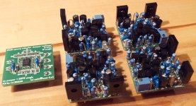
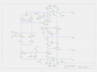
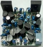
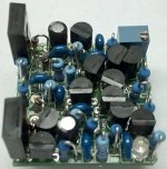
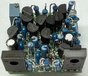
Another discrete opamp with high performance - unity gain stable. Through hole parts only.
MyDoa v3.1 (schematic) and some 20kHz distortion residual measurements compared to LM4562 and NE5532.
BR, Toni
MyDoa v3.1 (schematic) and some 20kHz distortion residual measurements compared to LM4562 and NE5532.
BR, Toni
Attachments
Another discrete opamp with high performance - unity gain stable. Through hole parts only.
Thanks - at first glance, it looks like a Blameless/JE990 derivative. The output stage looks like a Self Type I/II hybrid - will take a detailed look in LTspice in due course.
I would separate the biasing for the LTP and VAS CCSes - maybe just superstition, but I use separate JFETs for each CCS in my (SMD) FET990 derivative.
Would call it a "mini blameless" with added capacitance multipliers to increase the PSRR: my teachers are (the books of) D. Self and Bob Cordell and of course many users of the DIY community.
")
Separate CCS biasing hasn't shown any difference in simulation so I decided to keep it simple.
Spice files can be found in my amplifier thread - see link above.
Have fun, Toni
Attachments
Last edited:
Would call it a "mini blameless" with added capacitance multipliers to increase the PSRR: my teachers are (the books of) D. Self and Bob Cordell and of course many users of the DIY community.
Separate CCS biasing hasn't shown any difference in simulation so I decided to keep it simple.
Hi,
Testing the Schlozaur's follower (in Self's "Small Signal Audio Design", figure 3.17) I found that changing the 2-transistors current mirror to a 3-transistors Wilson improved the THD by 10 dB (a 4-transistors was disappointing).
Have you tested it on your circuit ?
Would call it a "mini blameless" with added capacitance multipliers to increase the PSRR...
Purely a parts-selection recommendation: C7 and C8 in the capacitance multiplier could be Black Gate PK, or even better - Wima MKS2XL in 5mm pitch.
I noticed that it requires a ground pin, so it can't be DIP8 single compatible unless one of pins 1, 5 or 8 are re-purposed as ground, or a 9th pin is used. Of course, API2520 pinout is just fine.
I found that changing the 2-transistors current mirror to a 3-transistors Wilson improved the THD by 10 dB (a 4-transistors was disappointing).
I too found some simulated improvement in THD20 with the Wilson CM in the FET990, but I do not remember comparing the 3- and 4-BJT versions. I also found some improvement by cascoding a JFET CCS for the LTP.
Purely a parts-selection recommendation: C7 and C8 in the capacitance multiplier could be Black Gate PK, or even better - Wima MKS2XL in 5mm pitch.
...
Of course one can use other capacitors...
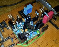
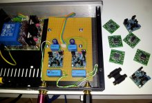
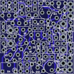
I have used electrolytics of good quality and they are cheap too. Wima with 5mm pitch would be too big for current layout. See attached pcb picture.
Attachments
Yes - and removed it due to part count. Maybe I should retry with 3 transistor CM using "national measurements method". During design phase I haven't used this measurement method...Hi,
Testing the Schlozaur's follower (in Self's "Small Signal Audio Design", figure 3.17) I found that changing the 2-transistors current mirror to a 3-transistors Wilson improved the THD by 10 dB (a 4-transistors was disappointing).
Have you tested it on your circuit ?
Attachments
Last edited:
What other types of distortion are builders measuring apart from harmonics and noise? Normally, I consider individual orders of harmonics to be of value, but where the distortion is -90dB or better, I find the orders lose all relevance as it is quite literally below the hearing threshold. I'm just kind of curious about the other types, because in the search for lower harmonic distortion and noise, are we sacrificing sound quality in some designs by accidently raising the level of a different distortion?
... in the search for lower harmonic distortion and noise, are we sacrificing sound quality in some designs by accidently raising the level of a different distortion?
The elephant in the drawing room is IMD - Intermodulation Distortion. There's some evidence that perceived sound quality is higher when IMD is low, even if THD is moderately high.
The subjective factor that is correlated with low IMD is usually described as "definition".
a few people have seen that elephant - its actually quite often reported on - you have to have pretty narrow blinders on to miss such discussion
most usually people say such things because they want to beat the old moldy strawman that someone out there really believes one single operating point THD number is everything - so they can dismiss any set of numbers, objective evaluation technique
most usually people say such things because they want to beat the old moldy strawman that someone out there really believes one single operating point THD number is everything - so they can dismiss any set of numbers, objective evaluation technique
99% of the needed distortion information is gathered by a traditional single-tone THD/THD+N measurement, where the source is swept over an appopriate range of frequencies (say 10-100k Hz) and levels (say from full scale down -40 dB of that). There are rare cases where this does not catch a significant nonlinearity mechanism (e.g. near the bandwidth limit of the DUT, where the harmonics may be filtered out), and this can be fixed with a two-tone IMD measurement. Multi-tone measurements are good for high-speed production testing, but I'm not aware that these should be of any interest for R & D.
Samuel
Last edited:
I'm not sure if I agree with (or even fully understand) what Samuel Groner asserts. In principle, dual-tone (or even multi-tone) IMD simulations can be carried out in Spice, if you have sufficient patience to run it for enough cycles that an integral number of both (all) waveforms are simulated.
Of course, this is based on the assumption that Spice simulations are a valid part of R&D, which I accept (and wholeheartedly embrace).
Of course, this is based on the assumption that Spice simulations are a valid part of R&D, which I accept (and wholeheartedly embrace).
people do the 2-tone IMD, multitones with real hardware too - including Groner
Hofer and Cabot at AudioPrecision have several articles that are useful if you want to know how audio systems are measured by actual professional engineers, what test signals are "standard" nowadays (for many decades actually)
as you increase the number of frequencies in a multitone you have to decrease the level of each frequency component - greatly reducing sensitivity for higher order distortion mechanisms
single sine harmonic distortion and 2-tone IMD sweeps in level and frequency do find almost everything unless you have deliberately designed multiple frequency filters feeding analog multipliers and summing them in your output
I use 2-tone in sim quite often, with a modern PC, LTspice it really isn't a problem to do with fine enough time step, long enough # of periods
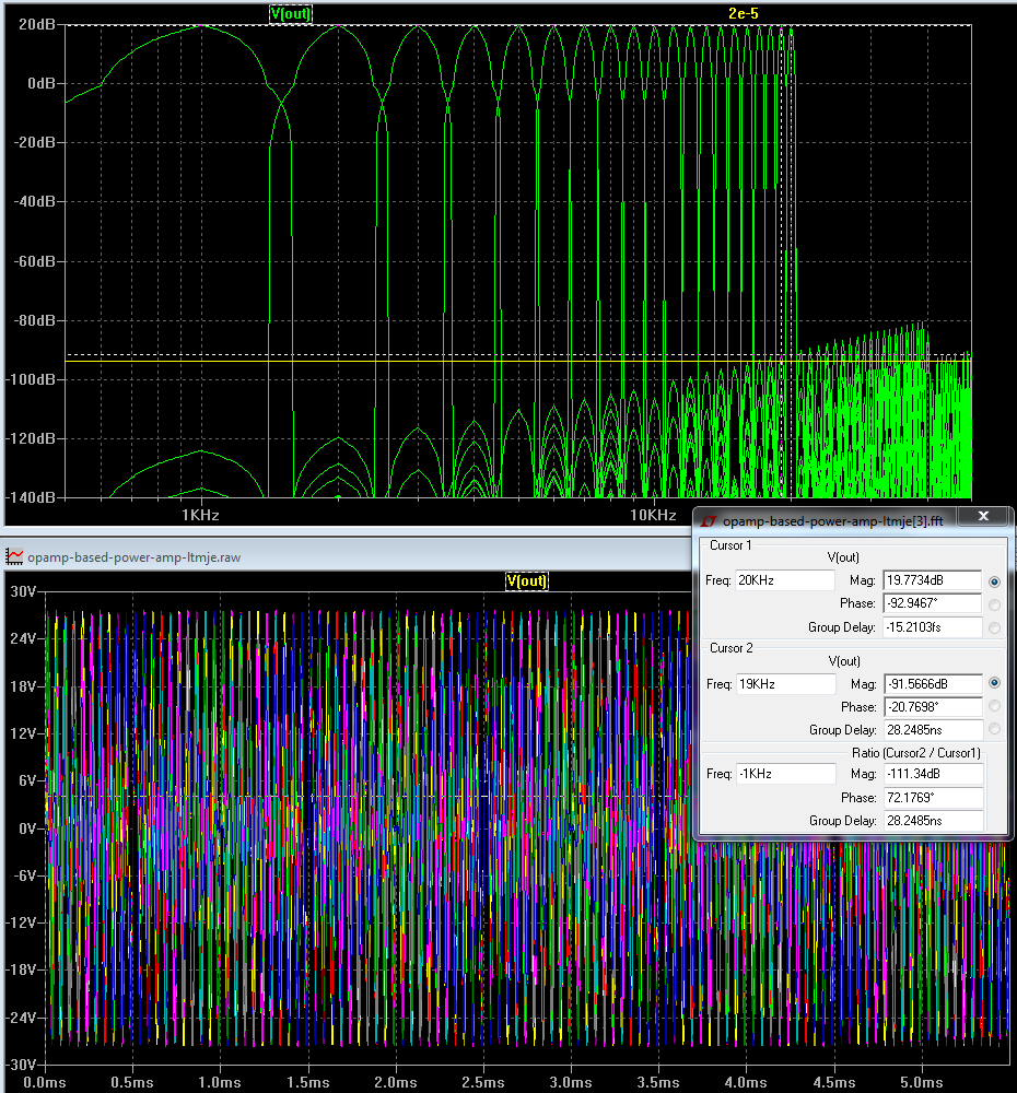
looking at the .tran distortion sim a interesting test is to use 2 sine inputs in series, 1:1 level of 600mV each to give near full output, fix one at 20 KHz, step the other from 1k to 19k in 1 kHz steps - the critical measure of quality is the IMD products below 20 kHz - also has the harmonic distortions of the lower tone
when this stepped 2-tone is done you can plot the combined fft, see just how "bad" the "rising distortion with frequency" is (not)
the yellow line is ~ -120 dB re the peak of the combined 2 tones
you can see all audio frequency harmonics of the 1-19 kHz stepped frequency tones and the IMD difference products of all orders with the 20 kHz constant tone
all audio frequency distortions just barely breaks above -120 dB below the combined 2 tone peak amplitude in the 18, 19 kHz bins - with the original op amp
the level of all of the audio band distortions are all inaudible - below human hearing threshold in quiet if the speaker were giving 120 dB SPL with the amp's full output
with higher loop gain op amp you can keep every audio frequency distortion product below -120 dB in the sim
Last edited:
Could you post a pic of your mod? Or better still the *.ASC file.Testing the Schlozaur's follower (in Self's "Small Signal Audio Design", figure 3.17) I found that changing the 2-transistors current mirror to a 3-transistors Wilson improved the THD by 10 dB (a 4-transistors was disappointing).
As you've 'improved' it, it is your copyright .. though I'm sure Doug won't mind even if you posted his original pic. as its for education.
I'm not sure if I agree with (or even fully understand) what Samuel Groner asserts. In principle, dual-tone (or even multi-tone) IMD simulations can be carried out in Spice, if you have sufficient patience to run it for enough cycles that an integral number of both (all) waveforms are simulated.
Of course, this is based on the assumption that Spice simulations are a valid part of R&D, which I accept (and wholeheartedly embrace).
First, while Spice simulations are a valid part of R&D, and essential in IC work, they are only as good as the models used in them. In my experience the only times when the spice distortion matches the real parts is when its gross. It doesn't exist as a real thing until you build it. That is when you find the many real world challenges to the circuits. That is also when the .0001% THD of the simulation becomes .05% and defy's every effort to fix it.
Distortion measurements should not be confused with the nature of the circuit. They are symptoms, not causes. The cause is the non-linearity of the circuit and that non-linearity alters the input generating the distortions. Both IM and THD react predictably to a nonlinearity. Its possible to calculate the distortions, both IM and THD from a known nonlinearity. Its very hard to have significant IM on a 19KHz + 20 KHz without significant THD on a 20 KHz tone. The system may prevent you seeing the THD (ADC's for example) but its still there.
IM is actually easier to measure at low levels because its a predictable frequency domain aspect and narrow band filters work well to get lots of dynamic range. THD is way harder with all the other noises you find when looking at low levels.
- Home
- Source & Line
- Analog Line Level
- Discrete Opamp Open Design