Well the power amp portion defies time and still sounds all right, and the application is driving AKG C1000 headphones and amplifying the adjustable output of a Roland RD-500, so I don't really need gain and input switching anyway.Past Deoxit and disassemble/clean with eraser etc?
Parts not avail either, so need to jump on the S/S, relay and CS3318 bandwagon.
Need a pre-amp, with no pots, switches, in the sig path, got one for sale")
Someone in here was disparaging the design, which is hilariously low-budget, a single-ended input stage and with diode biasing and lots of electrolytics. But it sounds adequate to my ears. The person also warned me that the adhesive that secures the bulk caps is unstable and will eat into the cans with certain disaster to follow. I saw no signs of this after more than 30 years, so perhaps I got a unit where things were properly cured or something.
I have the habit of taking things apart to improve them and winding up abandoning the carcass. I have a Ming Da tube amp on the floor that I had just about installed a voltage regulator in, already having modified it substantially. In storage I have a JBL SA-600 in pieces, the design that Bart Locanthi attempted to patent and one of the early solid-state designs that didn't sound too bad. Oh, and an old Meridian two-piece power amp that I traced out the schematic for and started to redesign --- or did I finally toss that out?
I'm gradually learning to leave things well enough alone.
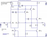
Here is the first output buffer that was simple enough without compromising performance. I'm still looking at G = 10 and up performance because there is a some fine scale work needed to insure stability at low gains. Also as bcarso points out there might be an opportunity for power on latch-up so there might be a simple clamp needed somewhere. I don't think this is a big problem.
The output stage is biased all the way back from the input (via Q15 and Q16). If you follow the signal path this gives a feed forward slew boost directly to the output, unfortunately this only works in both directions if one of the fully differential input stages is used.This idea appears in many current feedback amps and this single gain stage approach provides the same opportunity. I will eventually repost all three ideas for input stages including this output stage. The other two versions were the Rush cascode and the complimentary version with hard to get FETs.
All versions rely on the input biased at 5mA per side. R8 provides trim of output bias which should be at 8mA. This gives a total supply current of 25mA. R19 should be chosen to give ~1mA for the supply voltage used. The values of R7 and C1are open to experimentation to vary GBW product and slew rate.
Nothing is chiseled in stone I'm sure there are numerous choices of devices that will work. At this waystation things look pretty good for G = 10 and up, 600 Ohm and 1000pF drive. Considering all the diode connected transistors could just be diodes there are only 16 or 18 active devices needed.
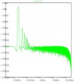
Attached are 20k 20V p-p THD and 100k square wave response (600 Ohm load)
Suggested reading --> Distortion Cancellation Amplifier System patent by S.Wurcer; 1992. US5166637 A
Thx-RNMarsh
google patents Patent US5166637 - Distortion cancellation amplifier system - Google Patents collects all the pages, doesn't require .tiff can view/save as pdf https://docs.google.com/viewer?url=patentimages.storage.googleapis.com/pdfs/US5166637.pdf
of course I prefer a feedback interpretation: http://www.diyaudio.com/forums/soli...terview-error-correction-337.html#post1513928
the cancellation cap isn't smart enough to only feedback distortion - it provides a local positive feedback, "canceling" the internal compensation, giving more local loop gain around the output stage
Last edited:
> He is active on the Forum, but his last post to THIS thread was Post #2625 on 25 Jan 2013
Yes, it's been a while since I posted, but I every now and then keep an eye of what is happening here.
People who knows me knows that I like building simple FET circuits.
As I posted earlier, our team built a 10x10 prototype of the Kaneda circuit.
But it is too small to solder for most, and too tidious to adjust to make it a public project.
While I am certain the latter designs are equally nice in performance, they become too complex and hence large to build in 10x10 footprint.
Also others have been making an excellent effort with SMD PCBs and builds, so I stayed on the side line.
> It would be really nice if the first post could be edited with some of this info of who is doing what, and with relevant post #'s in the thread.
I didn't even know that I still have editing right.
If you tell me what you wish to put there, I can give it a go.
BUT there are tons of information here, so how much of those can you / would you want to place in post 1 ?
Keep it going. It is a great thread.
Patrick
I have the habit of taking things apart to improve them and winding up abandoning the carcass.
...
I'm gradually learning to leave things well enough alone.
Yeah, same affliction here, though I'm sufficiently obsessive-compulsive to finish a project before switching to another. That minimizes the number of carcasses on the floor, though there is still a Technics integrated amp on the floor that needs some major organ transplants.
This was my latest project - about an afternoon of desoldering/soldering, and well worth the effort:
http://www.diyaudio.com/forums/digi...dge-audio-azur-c540-cd-mod-2.html#post3612640
OK, now back to simulating topologies. Here's a Kaneda variant with active loads in the LTP, differential VAS and a Class-A output stage which borrows ideas from the Cantilevered Cascode Buffer I posted earlier. The upper NPN in the output totem-pole runs at (nearly) constant current, while the lower NPN provides all the output current swing, just like the CCB.
It has respectable distortion numbers, given that it uses only 3 JFETs and 6 BJTs - H2 is below -100 dBr at 4V output amplitude into 600R. Some further elaborations are possible to reduce H2.
It has respectable distortion numbers, given that it uses only 3 JFETs and 6 BJTs - H2 is below -100 dBr at 4V output amplitude into 600R. Some further elaborations are possible to reduce H2.
Attachments
>
As I posted earlier, our team built a 10x10 prototype of the Kaneda circuit.
But it is too small to solder for most, and too tidious to adjust to make it a public project.
While I am certain the latter designs are equally nice in performance, they become too complex and hence large to build in 10x10 footprint.
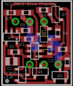
This is not quite 10x10 - it's about 12.7mm by 15 mm, but with no additional vias and almost entirely on a single side (the rail-to-rail bypass on the solder side is optional, in which case this is a pure single-sided layout). It could be crunched down a bit more by using SOT323, 363 and dual JFETs, but as it stands now it represents a reasonable tradeoff between ease of assembly and size. The dual BJTs shown are Rohm duals that are readily available.
The schematic is the Kaneda variant shown in the previous post.
Attachments
High Voltage Depletion FETs
Guru Wurcer, I believe one of your original plans for SWOPA was to use the input stage for a 100W 8R amplifier.
This would need High Voltage Depletion FETs for the input cascodes.
I think some suitable devices including some depletion MOSFETs were unearthed.
Would you or anyone else remember what these were ... especially if they have good SPICE models?
I think some suitable devices including some depletion MOSFETs were unearthed.
Would you or anyone else remember what these were ... especially if they have good SPICE models?
Supertex makes (or used to make) a line of depletion MOSFETs like the DN2540, etc. There were probably a few in TO92 packages. Other vendors were Ixys and Clare, but not sure of current production status.
Edit: Apparently still in production at Ixys (which owns Clare), in very nice SMT packages:
http://www.ixysic.com/Products/FET.htm
Infineon also has some BSS family parts like the BSS126, 129, 149, 159, 169...
All of these are n-channel only - I don't think there has ever been a depletion-mode p-MOSFET fabricated.
There are also a few Japanese n-channel depletion JFETS with (relatively) high Vds(max) ratings - Toshiba 2sk373 at 100V, and a Sanyo part that does 80V, among others. Both are nearly obtainium now.
Last edited:
A potentially "quick" question: Any of these designs have GBW of >= 100 MHz and low noise data?
SWOPA and kgrlee's FET990 variant could get to 50 MHz GBW, maybe more - but 100 MHz is probably outside their envelope. All the others are slower, AFAIK.
Low noise is not a problem - any of the JFET-input designs can use low-noise devices and surpass almost any monolithic.
I recall playing with simulations that got GBW up to the 50 MHz - 60 MHz range by using fast transistors and adjusting passive component values. I could tell it was starting to get sensitive to active device parameters, so might require some pre-selection or matching of active devices to reach that performance level on a physical assembly.SWOPA and kgrlee's FET990 variant could get to 50 MHz GBW, maybe more - but 100 MHz is probably outside their envelope . . . .
100 MHz might be possible if you're willing to give up unity gain stability. The ability to modify the compensation scheme to suit an application is one of the attractions of a discrete design like this. That's why I brought out the main compensation node to an external connection when I did my PWB layouts. (See Posts #2909 and #2656.)
Dale
What application needs this?Any of these designs have GBW of >= 100 MHz and low noise data?
Hi all,
& thanks for replying. An oscillator would be interesting although I don't really know how to design one with low THD which would be my aim here. In this case I'm mostly curious - maybe you have a part of your mind that often "searches" for new & better solutions - this is what happened here as I've found this thread's designs interesting though haven't had the time to read all of it.
Greetings,
Jesper
- Home
- Source & Line
- Analog Line Level
- Discrete Opamp Open Design