linux, what current are you running in the output stages?
I suppose, electrical.
")
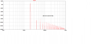
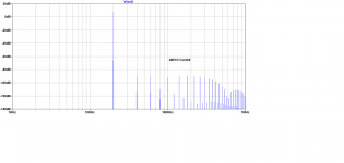
Voltage Followers into 15R @ 3.162Vp
Here's what old topologies can do with some dirty tricks. THD plots for Voltage Followers @ a headbanging 3.162Vp 20kHz into 15R.
#2060 is running 7mA through the output devices. SW-OPA 10mA. I've used Cordell's 4401/3 models cos they are worst case for both distortion & stability in these sims.
You can see the characteristic rising spectrum of crossover distortion with SW-OPA but remember these products are 90 - 100dB down.
More Iq and medium power devices will reduce crossover but #2060 will always show less crossover at the same current.
The best ADs/DAs today are juu..ust 20b so 117dB [*] is about the measurement limit today for distortion residuals. See Scott for his experience of a Panasonic AD with true 24b performance that was declared un-manufacturable.
____________________
Anyone know how to make LTspice produce a distortion residual waveform?
I like to look at this with old fashion THD instruments. You can usually see if THD is due to crossover, 'gm doubling', poor PSR etc.
[*] You can go a bit better with sophisticated 'averaging' and DSP but only a bit. The 'noise floor' on FFT measurements is NOT the same as what distortion products you can measure. That depends on the AD.
Attachments
Last edited:
____________________
Anyone know how to make LTspice can produce a distortion residual waveform?
I liked to look at this with old fashion THD instruments. You can usually see if THD is due to crossover, 'gm doubling', poor PSR etc.
Many times I use banks of notch filters in sim, and besides showing the residuals in the time domain I also get a cross-check on the veracity of the DFT. Of course the notch filters must be given plenty of time to settle.
In a recent study of state-variable-filter-based oscillators, I found the DFT refusing to give anything close to the right answer, very much overestimating the distortion. I knew something was screwy when running two matched oscillators in opposing polarity had no effect on second-order when the outputs were differenced!
This wasn't by any chance Great Guru Baxandall's swept oscillator using semiconductor junctions?In a recent study of state-variable-filter-based oscillators, I found the DFT refusing to give anything close to the right answer, very much overestimating the distortion. I knew something was screwy when running two matched oscillators in opposing polarity had no effect on second-order when the outputs were differenced!
John Vanderkooy recently did an analysis and update in homage for AES.
I had the dubious honour of getting this to work for production in Jurassic times. Though I worship GGB on my knees 5x a day, his designs often required extensive tweaking by expensive virgins in production.
This wasn't by any chance Great Guru Baxandall's swept oscillator using semiconductor junctions?
John Vanderkooy recently did an analysis and update in homage for AES.
I had the dubious honour of getting this to work for production in Jurassic times. Though I worship GGB on my knees 5x a day, his designs often required extensive tweaking by expensive virgins in production.
No semi junctions involved for tuning, but I had remarked to Chris Paul that I'd played around with low distortion oscillators many years ago, having conceived of a stabilization scheme involving the trig identity, taking advantage of the presence of quadrature outputs for the SVF. I later noticed this approach published in the classic opamp book of Tobey et al.
And the gotcha for the trig identity approach is making really good four-quadrant multipliers to square the quadrature outputs.
The main trick with oscillators with a lot of internal loss (as opposed to very-high-Q resonators like crystals) is to make the required amplitude stabilization intervention as small as possible, and avoid the feedthrough of garbage from the detector of amplitude. Hofer and company did this in a clever way as to make frequency changes more rapid without degrading distortion too much (there is a patent) by feeding some of the control signal ahead to cancel.
The late Jim Williams got to explore these issues late in life (as it turned out, sadly) when all he wanted was a very low distortion oscillator, and characteristically figured he could do it on his own. IIRC it was a somewhat humbling experience.
jcx has a THD residual solution for ltspice
http://www.diyaudio.com/forums/software-tools/101810-spice-simulation-37.html#post1333137
http://www.diyaudio.com/forums/software-tools/101810-spice-simulation-37.html#post1333137
Any output waveform can represent an expression of any level of complexity, so simply subtract the input from the output, with multiplier and phase adjusted appropriately, is a simple way to do the job ....Anyone know how to make LTspice produce a distortion residual waveform?
Frank
Last edited:
linux, what current are you running in the output stages?
LTSpice says:
For J113/J176 and 47R 47R: 8 mA
For J111/J175 and 100R 100R: 16.6 mA
For J111/J175 and 150R 150R: 13 mA
For 2sk170bl/2sj74bl, no source degeneration and 1x 1n4148 between gates: 2.9 mA
In all cases, the VAS current sims as 3.25 mA.
I'd go with selected J111/J175 with Idss around 20 mA. TO18 2n4391 runs about $1.50 and 2n5114 at least $5 on EBay.
It appears both parts are being made by Linear Integrated Systems, who however only gives an ambient rating of 500mW for the P part and evidently does not tie the gate to the case like the 4391. Older 5114s definitely had the gate connected to the case.
InterFET also has current-production TO18 2n5114s with the gate connected to the case, but rated at 500 mW Pd.
Is there a cheaper TO92 PN5114 or similar?
InterFET also has current-production TO18 2n5114s with the gate connected to the case, but rated at 500 mW Pd.
Is there a cheaper TO92 PN5114 or similar?
The 500mW is an ambient rating I think, so if the gate is tied to the case the comparable-to-4391 rating should obtain, not that I would run it that high.
Based on my old Siliconix databook, the J174 series is the same chip as the 5114/5115/5116. They state 500mW for the TO-18, 360mW for the TO-92, without a case temp rating.
Interestingly, the same databook gives ONLY the 1800mW case temp rating for the 2N4391. The chip is the same as for the J111 series, which only shows the 360mW ambient rating.
So, it is probably fairly safe to assume that a case temp rating for a proper 2N5114 would be 1800mW.
... Based on my old Siliconix databook, the J174 series is the same chip as the 5114/5115/5116.
...
2N4391. The chip is the same as for the J111 series...
Thanks - great, that settles it. I'll go with J111/J174/J175 (all appear to be multiple-sourced, and I have access to quantity of Vishay/Siliconix J175 locally, which makes the Idss selection easier).
I'll make the layout such that the T018 FETs can also be fitted interchangeably, which will allow those who want a premium BoM to use them.
The only limitation now is that the Vds ratings don't allow /- 24V rails, but that can be solved with a BJT cascode a la Burson.
FWIW, there's an EBay seller in Portland, OR who's offering 100-unit lots of Fairchild PN4391 in TO92 for USD 13.95, free shipping in the US. Those in the US may want to grab a few lots - I can't bid since he won't ship international.
Mouser's 250 piece price for the J111 (TO-92) is 9.9 cents US, the 100 piece price just a little higher than the eBay seller. EUVL pointed out to me that the NXP parts in this family have a 5V higher rated Vdg, but alas they are only supplying them in SM. By the way, the gate lead on SOT-23 is usually the closest thermal path to the chip, and since it is so short, if you can effectively contact it thermally, you can cool the chip quite effectively.
George just posted Baxandall Power Amp Design on another thread.I've been studying Jerald Graeme's "Feedback Plots define Op Amp AC Performance", sboa015.pdf from the TI library, while playing with stability of the FET990.
There are 2 considerations for stability which also lead to 2 definitions of 'Unconditional Stability
- Stability with different levels of NFB. This old warhorse is fairly (??!) straightforward. Easy to have a different version for gain less than 3x etc or a single NPO ceramic to change. These are my C4/5 recommendations in post #2060. Graeme helps me formalise much of my experience & thinking and introduces at least one new dodge. Prof. Cherry is excellent if you ken reed, rite & kont.
- Stability with load. This is the important one with Power Amps as you don't often tweak NFB but you do have loadsa different loads. Output Inductors are a big help for this but for a supa dupa GP OPA, SM inductors are truly evil and muck up your 1 ppzillion THD for various reasons. But easy (?!) enough if your noise gain is fixed.
As with all of the Great Guru's stuff. his clarity and accuracy goes deep and will reward close study for years. The stability stuff starts from the 3rd article.
Jan Didden is reprinting it in Linear Audio with Self's stuff. Here's a sample of Baxandall's Last Words The Baxandall Papers
Scott,
You just brought up a subject that you can obviously answer for me. When building a board and using rosin core solder should the hobbyist clean the boards after assembly? I have never done this and can say that I am not an EE so perhaps I have just been lucky or stupid and have never seen a failure because of flux. If I should indeed clean the boards what is the correct solvent to use? 1,1,1,T is long since not allowed and I wonder what is the best solvent for this purpose. Sorry for going off topic here, but I have often wondered if this is only a problem with the never non-lead based solders or all solders with a flux core. Built a Heathkit clock when I was a kid and it worked for almost 40 years before the digital display started to burn out. What is the failure mode action here with the flux?
You just brought up a subject that you can obviously answer for me. When building a board and using rosin core solder should the hobbyist clean the boards after assembly? I have never done this and can say that I am not an EE so perhaps I have just been lucky or stupid and have never seen a failure because of flux. If I should indeed clean the boards what is the correct solvent to use? 1,1,1,T is long since not allowed and I wonder what is the best solvent for this purpose. Sorry for going off topic here, but I have often wondered if this is only a problem with the never non-lead based solders or all solders with a flux core. Built a Heathkit clock when I was a kid and it worked for almost 40 years before the digital display started to burn out. What is the failure mode action here with the flux?
Last edited:
Back off- or on-topic, depending on your inclination. The posted circuit uses a p-JFET, it's only simulation circuit and the JFET models may be unrealistic - but still, it sims with remarkably low THD20 of around -120 dbr at 4V amplitude into 600R. This is about the best I've ever managed with just 12 actives.
I've been busy and missed this, looks like a great idea. You're in good hands here.
Scott,
You just brought up a subject that you can obviously answer for me. When building a board and using rosin core solder should the hobbyist clean the boards after assembly? I have never done this and can say that I am not an EE so perhaps I have just been lucky or stupid and have never seen a failure because of flux. If I should indeed clean the boards what is the correct solvent to use? 1,1,1,T is long since not allowed and I wonder what is the best solvent for this purpose. Sorry for going off topic here, but I have often wondered if this is only a problem with the never non-lead based solders or all solders with a flux core. Built a Heathkit clock when I was a kid and it worked for almost 40 years before the digital display started to burn out. What is the failure mode act action here with the flux?
I measured steady .5 to 1V potentials on open pins under power which means leakage (we are dealing with FET's here). The lead free flux seems much worse than before. We use a heated mixture of isopropyl and DI water in an ultrarsonic cleaner. At home usually a brushing with isopropyl followed by a wash in DI is enough (blowdry to speed up the process).
We have been having a lot of problems lately with bad characterization data on high impedance circuits and I don't feel like wasting any time unnecessissarily.
EDIT - Please no horrible solvents necessary, one benefit of the new flux is that ordinary solvents seem to work.
Last edited:
Thank you Scott. So the flux is actually conductive then at the levels you are talking about. Glad I can still get lead solder, I have had nothing but trouble with the newer solders, they just don't flow very well. So Isopropyl alcohol and Deionized water then. Thank you for the information.
- Home
- Source & Line
- Analog Line Level
- Discrete Opamp Open Design