Hey guys,
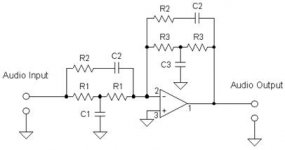
I have really been researching the LTC and still have quite a few questions. First, here are the component values I have settled on and the circuit I want to use (see attached for circuit schematic).
C1 - 2.157μF
C2 - .068μF
C3 - .4014μF
R1 - 7.17kΩ
R2 - 39.96kΩ
R3 - 38.53kΩ
Now for the questions:
1. What is the difference between an opamp and amp? What would a traditional car amp be considered? What would a traditional home amp be considered?
2. Where exactly does this circuit get placed in regards to the signal source, amp, and driver? If the placement is between the amp and driver, as I believe it to be, how many watts can this circuit handle? How can I determine and appropriate this?
3. When selecting components for the circuit, what is the best way to determine the necessary component values to approximate calculated values with the least error?
4. When selecting resistors, how do I determine whether the resistors need to be 1W, 2W, 5W, etc? How do I determine whether the resistors need to be carbon, flameproof, etc?
5. Same question but in regards to the capacitors and their appropriate differences.
6. Where could I go to have this circuit built or bought without purchasing it from Australia?
Even if you can only answer one, or part of one, question I would appreciate it.
Thanks,
Tony
You have a whole lot to learn before you will be able to implement this circuit properly.
Start here....
Operational amplifier - Wikipedia, the free encyclopedia
Linkwitz Transform Subwoofer Equaliser
Start here....
Operational amplifier - Wikipedia, the free encyclopedia
Linkwitz Transform Subwoofer Equaliser
You have a whole lot to learn before you will be able to implement this circuit properly.
Start here....
Operational amplifier - Wikipedia, the free encyclopedia
Linkwitz Transform Subwoofer Equaliser
I have read all this.
OK, You are talking about building a Linkwitz Transform circuit to equalize a sealed woofer that has very low Q, correct?
I don't want to sound discouraging, as I welcome everyone to DIY, but you are starting way over your head. We can easily answer all your questions, but I am afraid it would not be helpful.
To get started learning electronics, you need to start with the basics. Probably a lot of us started by building kits. ( we had Allied, Dynaco and Heath in those days) and most probably read Popular Electronics as kids. You would be surprised here how many may have degrees in electronics, built ham radios, or tinkered as little kids. I built my first crystal radio at about 7 and for many, that was late. But, you can do this yourself! You don't have to have a degree. It just helps.
The Linkwitz Transform Circuit is a very simple in execution, but you must understand what it is trying to do, and how it works with the speaker. It is part of the entire amp-speaker system. It is not just some bass boost. Most sub amps have some amount of bass boost built in. It would not be a LT as it would not be correctly calculated for a specific Q.
Even if you chose not to buy boards from ESP, his documentation is very good. A far more advanced discussion would to be to go to the source and visit Siegfried Liknwitz's WEB. If cornered, I bet a lot of folks here shudder when trying to understand s-plane, so don't get too discouraged when you see high level engineering math. It is a good to see what can be learned. Electronics is actually pretty straight forward. E=IR.
Quick answers. Op-amp here means an integrated circuit that behaves as an operational amplifier. For this use, you would want metal film resistors in 1/8 or 1/4 Watt. The circuit goes between the preamp and the power amp. It also needs a power supply. Caps are horribly complex little buggers, but you want to use a film type with a voltage at least double what the circuit would ever see. There are several web based sites that will calculate the values for you. If you don't want to buy boards, you build one of perf board. You don't need to be that precise in values because the speaker is not that precise. You don't know what the target values would be unless you can measure some parameters of the completed speaker.
Now, unfortunately, that does not help you build one. I just want to be realistic. I suggest you buy a car stereo crossover or amp with bass boost built in, then we can take some time to get you started properly in DIY electronics. Safer that way. Of course, one of the best approaches is to take basic electronics at your friendly community college. Something like a CMoy headphone amp would be a good start. Or any of the Radio Shack basic kits.
This is a great hobby. It can keep your mind going. The first time you build a circuit that works of your own design is a wonderful feeling. Of course, the first time you fail to keep the smoke inside the wires is not so wonderful. We have all been there and revisit that space more than we care to admit.
OK, You are talking about building a Linkwitz Transform circuit to equalize a sealed woofer that has very low Q, correct?
Yes
To get started learning electronics, you need to start with the basics. Probably a lot of us started by building kits. ( we had Allied, Dynaco and Heath in those days) and most probably read Popular Electronics as kids. You would be surprised here how many may have degrees in electronics, built ham radios, or tinkered as little kids. I built my first crystal radio at about 7 and for many, that was late. But, you can do this yourself! You don't have to have a degree. It just helps.
First, thanks for not just dismissing me. I like to consider myself bright and a fast learning, I just need the direction. The problem I run into is the inability to find the resources to learn... I have taken Physics 1 and 2 at the CC, along with my degree courses, but its apparent just a few more classes are required ha. And I know there is a lot of learning involved, and the direction is what I need.
Similarly, I know this is suppose to be a fairly "simple" circuit with pretty impressive results, so it interests me. I would not mind buying a pre-built circuit, would actually prefer it, but buying it internationally I would like to avoid.
Thanks again, this was a lot of help.
Here is a link to a site were you can get a p.c. board and full information for a L-T circuit...
Linkwitz Transform Subwoofer Equaliser
rcw
Linkwitz Transform Subwoofer Equaliser
rcw
We all had to get started somehow. ")
You may not have noticed my comment, you also need a power supply. These too are pretty simple. You need a basic small plus and minus 15 to 17 volt supply. Simple three terminal regulators will work fine. There are many kits for this on the web. Of course, playing with a power supply means playing with line voltage and though not at all hard, there are a lot of little details to be know. There is a reason for those UL and CSA stickers on the backs of things. ( My apologies, I don't know the EU program).
By adding sufficiently large blocking caps, you could just run it off a few of 9V batteries. At least this would get you started easy, cheap and safe. ( before anyone else jumps in, yes single ended supply for batteries unless you build an artificial ground as one battery will drain quicker than the other and cause big offset issues. I am trying to keep this simple)
For an op-amp, just use a normal NE5532. More than good enough. Heck a good TLO74 is fine. You can hard wire this up on a good old vector board along with the power supply.
I don't know your location, but by far the best way to get going is with someone looking over your shoulder. There are so many little details we all forget to mention. I was very lucky that my father is an EE so we spent many an hour at a chalk board where I learned my basics. A CC night class or three ( thinking back, Basic AC/DC, Devices, Circuits.... ) would probably get you going. You are probably way ahead of the typical ET student as you will have had the math. (Tip: In electronics, we use "j" instead of "i" for the sqrt of -1.) Really too bad we don't have Heathkit anymore. Nothing like seeing physically how things are put together. Most "DIY" kits are just a main board leaving it up to you to deal with cabinets, power and safety issues.
To use the LT, you do need to know the target Q and response. This is why ESP also has the "sub controller" that is variable so you could tune it by ear. The LT requires you know the speaker.
back to designing and assembling the Linkwitz Transform.
You need the T/S parameters of the speaker.
You need the box that the speaker will be fitted into.
You need the "parameters" of that completed boxed speaker.
You need the parameters that you want that speaker box transformed to, i.e. the target parameters.
Then you plug all your various numbers into Linkwitz's formulae.
Start by giving us the speaker and box data.
Hey guys,
1. What is the difference between an opamp and amp? What would a traditional car amp be considered? What would a traditional home amp be considered?
2. Where exactly does this circuit get placed in regards to the signal source, amp, and driver? If the placement is between the amp and driver, as I believe it to be, how many watts can this circuit handle? How can I determine and appropriate this?
3. When selecting components for the circuit, what is the best way to determine the necessary component values to approximate calculated values with the least error?
4. When selecting resistors, how do I determine whether the resistors need to be 1W, 2W, 5W, etc? How do I determine whether the resistors need to be carbon, flameproof, etc?
5. Same question but in regards to the capacitors and their appropriate differences.
6. Where could I go to have this circuit built or bought without purchasing it from Australia?
Even if you can only answer one, or part of one, question I would appreciate it.
Thanks,
Tony
Hi,
1) Op amps are line level not speaker level.
2) Its placed before the amplifier. It can be built into some amplifiers
by treating the inverting input as a unity gain point, advanced stuff.
(Assuming a differential LTP input topology.)
3) Sensitivity of circuits to component variation is an advanced topic.
Download the free TinaTi SPICE emulator, it does sensitivity analysis.
4) A question based on a wrong assumption.
Typical line level type components.
5) same as 4).
6) Lots of options, as the circuit is nowhere near as exotic as
you imagine. You need to understand why what is does can
be done pre the power amplifier easily, and why considering
doing it after the power amplifier is simply wrong on all counts.
FWIW LT's have nothing to do with low Q sealed boxes at all.
For these all you need is bass boost. LT's are for high Q sealed
boxes, where you first compensate for the high Q roll-off and
then define a new roll-off regimen of your choice.
Component values hardly describe what you are attempting to do.
rgds, sreten.
FWIW LT's have nothing to do with low Q sealed boxes at all.
For these all you need is bass boost. LT's are for high Q sealed
boxes, where you first compensate for the high Q roll-off and
then define a new roll-off regimen of your choice.
Actually, what's quoted above is not correct. Using the LT with a high Q sealed box is just one potential application of the circuit.
The LT generates a "response" that includes changes to both the signal amplitude and phase. The amplitude change can include boost and/or cut. It can be considered as a way to "transform" any second order response into any other one, and whether the original response has high Q or low Q doesn't matter at all.
-Charlie
I have a subwoofer electronics box that uses a 17VAC plug pack and a dual rail voltage doubler circuit, (also described at ESP), this removes any need to touch mains power.
The L-T circuit described is basically the one described on the Linkwitz site, and is constrained in what it can do by the expression he gives, to do anything outside that you need a more complex three op amp biquad circuit.
Classically an op amp was used in analogue computers to do operations and was a d.c. coupled amplifier with a inverting and non inverting input, the two rail power supply was to allow a lot of them to be d.c. connected with an acceptable offset voltage. Most of the cold war era military electronics was based upon analogue computers with op amps, and the integrated op amp was originally developed for this.
rcw
Hi,
I partly disagree with these defs.
The basic definition of an OPamp is a blackbox or building block featuring 2 inputs (one noninverting and one inverting) and one output. Additional inputs and outputs, say for power supply or reference pins may be omitted with in a first consideration.
The external circuitry connected to the Inputs and the output fully define the behaviour of the whole circuit. Voltage, current or power leves are not part of the definition.
So 1) and 2) describe at best half the truth. (Have read a lot of stuff about OPamps, but never came across an inv input defined as unity gain point???)
OPamps may be configured by their internal structure and external circuitry as amplifiers and the majority of amplifiers is constructed as Opamp.
But not every amplifier is constructed as OPamp, as well as not every Opamp works as amplifier (but differentiator, Integrator, Filter, Comparator, etc).
OPamps may come in discrete building form, as integrated circuit or a combination of both (e.g audio power amplifiers with integrated input stage and discrete power stage).
A expanded definition decribes the basic behaviour of an Opamp which in ideal theory are:
infinite gain, infinite input input impedance, and 0 output ipedance and no parasitic effects like noise, distortion etc.
jauu
Calvin
I partly disagree with these defs.
1) Op amps are line level not speaker level.
2) Its placed before the amplifier. It can be built into some amplifiers
by treating the inverting input as a unity gain point, advanced stuff.
(Assuming a differential LTP input topology.)
The basic definition of an OPamp is a blackbox or building block featuring 2 inputs (one noninverting and one inverting) and one output. Additional inputs and outputs, say for power supply or reference pins may be omitted with in a first consideration.
The external circuitry connected to the Inputs and the output fully define the behaviour of the whole circuit. Voltage, current or power leves are not part of the definition.
So 1) and 2) describe at best half the truth. (Have read a lot of stuff about OPamps, but never came across an inv input defined as unity gain point???)
OPamps may be configured by their internal structure and external circuitry as amplifiers and the majority of amplifiers is constructed as Opamp.
But not every amplifier is constructed as OPamp, as well as not every Opamp works as amplifier (but differentiator, Integrator, Filter, Comparator, etc).
OPamps may come in discrete building form, as integrated circuit or a combination of both (e.g audio power amplifiers with integrated input stage and discrete power stage).
A expanded definition decribes the basic behaviour of an Opamp which in ideal theory are:
infinite gain, infinite input input impedance, and 0 output ipedance and no parasitic effects like noise, distortion etc.
jauu
Calvin
Hi,
Some people are being picky about the details :
1) A LT is simply not needed for a low Q sealed box
ans its complicating a very simple bass boost facility.
LT in this case is the wrong way of looking at it.
2) The circuit described is clearly a line level op-amp circuit.
3) Typical unity gain op-amp high pass filter functions
can be built into amplifiers with gain by treating the
inverting input as the unity gain point.
Whether you've heard of this or not, some thought
will indicate its true, gain =1 at the inverting input
for series feedback. (Feedback path has to be
low enough impedance to drive the filter).
rgds, sreten.
Please take the following advice in the constructive manner in which I intended it. Many of your questions are of such as basic nature that I would have serious reservations about attempting to implement a circuit such as the Linkwitz Transform, if I were you. If you are truly serious about experimenting with DIY electronics, not merely building kits, than you really should take a formal course in electronics. Trade/vocational schools offer such programs. You don't to earn a degree, but a one year long part-time program could do wonders for your ability to do the things you seem to want to do.
Meanwhile, the following link to Elliot Sound Products could be of help for you immediate project. It's a Linkwitz Transform project for which where ESP offers a dedicated PCB.
Linkwitz Transform Subwoofer Equaliser
Meanwhile, the following link to Elliot Sound Products could be of help for you immediate project. It's a Linkwitz Transform project for which where ESP offers a dedicated PCB.
Linkwitz Transform Subwoofer Equaliser
Marchand Electronics sells what they call the "BASSIS", which is a fully adjustable LT equalizer type circuit. You can buy the populated circuit board from them for $90 including all pots for adjustment, etc. ready to use, or even one built with power supply and in a case if you want that. I have used them in the past and they work as advertised for low Q or high Q speaker applications!
subwoofer equalizer, bass correction equalizer, bass boost
-Charlie
subwoofer equalizer, bass correction equalizer, bass boost
-Charlie
As far as the performance parameters which define an ideal op-amp are concerned, input impedance, output impedance, gain, etc., those may be found widely on the internet.
In addition to those is that 'op-amp' is short for, 'operational amplifier'. 'Operational', refers to mathematical operations. Addition (summing), algebraic subtraction (difference), multiplication (logarithmic addition), division (logarithmic subtraction), integration and differentiation. The op-amp was invented to be the basic building block of analog computers. The first op-amp was built from vacuum tubes. While very susceptable to noise and other errors, analog computers can be exceedingly fast in performing such basic math operations. Digital computers are not nearly so susceptable to noise and other errors, and have replaced analog computers for those and other reasons, such as ease of programing. Op-amps are widely used today because they make for cheap and easy to implement linear gain blocks, mostly intended for signal amplification.
In addition to those is that 'op-amp' is short for, 'operational amplifier'. 'Operational', refers to mathematical operations. Addition (summing), algebraic subtraction (difference), multiplication (logarithmic addition), division (logarithmic subtraction), integration and differentiation. The op-amp was invented to be the basic building block of analog computers. The first op-amp was built from vacuum tubes. While very susceptable to noise and other errors, analog computers can be exceedingly fast in performing such basic math operations. Digital computers are not nearly so susceptable to noise and other errors, and have replaced analog computers for those and other reasons, such as ease of programing. Op-amps are widely used today because they make for cheap and easy to implement linear gain blocks, mostly intended for signal amplification.
Last edited:
Hi,
@sreten
Its not a matter of what I might have heard, but simply a matter of general conventions. If You had talked about ´configuring the OPamp as unity gain amplifier´ everybody with the slightest knowledge would have understood.
Its for sure not useful to confuse noobs by introducing Your personal set of conventions instead of common textbook conventions.
I´m surely no noob but I´n still not sure what You mean with unity gain point. Your explanation in 3) doesn´t help to clear the matter. What do You mean with gain=1 at the inverting input for series feedback and low impedance? The factor of "1" and "series feedback" define a noninverting configuration with only a connection between output and inverting input (no ground referencing for invIn) . So the signal is fed into the noninverting Input. Also the inputs themselves don´t feature a characteristic called ´gain´. The gain is a result of the OPs internal or openloop gain, feedback characteristics and which Input used as signal input.
jauu
Calvin
ps. after textbook convention the "unity gain point" defines the frequency where the OpenLoop Amplitude response has dropped to 1.
@sreten
3) Typical unity gain op-amp high pass filter functions
can be built into amplifiers with gain by treating the
inverting input as the unity gain point.
Whether you've heard of this or not, some thought
will indicate its true, gain =1 at the inverting input
for series feedback. (Feedback path has to be
low enough impedance to drive the filter).
Its not a matter of what I might have heard, but simply a matter of general conventions. If You had talked about ´configuring the OPamp as unity gain amplifier´ everybody with the slightest knowledge would have understood.
Its for sure not useful to confuse noobs by introducing Your personal set of conventions instead of common textbook conventions.
I´m surely no noob but I´n still not sure what You mean with unity gain point. Your explanation in 3) doesn´t help to clear the matter. What do You mean with gain=1 at the inverting input for series feedback and low impedance? The factor of "1" and "series feedback" define a noninverting configuration with only a connection between output and inverting input (no ground referencing for invIn) . So the signal is fed into the noninverting Input. Also the inputs themselves don´t feature a characteristic called ´gain´. The gain is a result of the OPs internal or openloop gain, feedback characteristics and which Input used as signal input.
jauu
Calvin
ps. after textbook convention the "unity gain point" defines the frequency where the OpenLoop Amplitude response has dropped to 1.
He means that the inverting input of a (modern) power amplifier will have essentially a replica of the non-inverting input's signal. Because it's at a relatively low impedance it can be used as if it were the output of a unity gain opamp for making active filters with the power amp.
Thanks,
Chris
Thanks,
Chris
- Status
- This old topic is closed. If you want to reopen this topic, contact a moderator using the "Report Post" button.
- Home
- Source & Line
- Analog Line Level
- Linkwitz Transforms