Hi all
I have problem with write source code for atmega8
Somebody can explain how use this SPI with Bascom
any body have ready schematic and source code for atmega8?
I need simple program for PGA2320 pot with two buttons volume up and down
I have as well
PGA2311
DS1803
MCP42100
Please all for help
I have problem with write source code for atmega8
Somebody can explain how use this SPI with Bascom
any body have ready schematic and source code for atmega8?
I need simple program for PGA2320 pot with two buttons volume up and down
I have as well
PGA2311
DS1803
MCP42100
Please all for help
Last edited:
PGA2311 programming
Go to the BASCOM site "http://www.mcselec.com/" and search for
Forum - MCS Electronics
This code was written for a PGA2313 which was a single channel part so it used a byte for the gain, whereas PGA2310,2311,2320 are two channel devices thus having 16 bits or a word. I have this all working but I am using an xmega MCU so the SPI stuff is different than what is in the example above. The example also used the software configuration a tyhe MCU was a '$regfile = "2313def.dat"' and your MPU ATmega must have a hardware SPI so that will be faster & have a bit less code, if you need it.
You can use the Volume variable to do the counting and just move it into the word variable, "Volume_word" as so, as I did for the xmega MCU
If Volume > 212 Then Volume = 212 'Volume Limit, max 255
If Volume < 0 Then Volume = 0
V_right = Volume
V_left = Volume
Reset Pga_cs 'Select Slave
Print #2 , Volume_word 'Send 16 bits to PGA2310
Set Pga_cs 'Deselect Slave
Change the code to make,
Dim V_right As Byte At Volume_word Overlay
Dim V_left As Byte At Volume_word + 1 Overlay
Hope this helps
Rick
PGA2311 programming & ckt
Why not make things easy for yourself, use a ATtiny2313 and wire your circuit up as in the example, I provided.
atmega8 is overkill for what you want to do!!
State your experience level? Have you ever built anything before?
If you want to learn BASCOM read, Intro doc at
www.techideas.co.nz
Device pinout
'---ATtiny2313 PDIP/SOIC--------------------------------------------------------
'1 (RESET/dW) PA2 20 VCC
'2 (RXD) PD0 19 PB7 (UCSK/SCL/PCINT7)
'3 (TXD) PD1 18 PB6 (MISO/DO/PCINT6)
'4 (XTAL2) PA1 17 PB5 (MOSI/DI/SDA/PCINT5)
'5 (XTAL1) PA0 16 PB4 (OC1B/PCINT4)
'6 (CKOUT/XCK/INT0) PD2 15 PB3 (OC1A/PCINT3)
'7 (INT1) PD3 14 PB2 (OC0A/PCINT2)
'8 (T0) PD4 13 PB1 (AIN1/PCINT1)
'9 (OC0B/T1) PD5 12 PB0 (AIN0/PCINT0)
'10 GND 11 PD6 (ICP)
From the code example
'Port allocations
'Port D
'0 - RS232 RX
'1 - RS232 TX
'2 -
'3 - IR Indicator LED
'4 - DOUT (SDI) Pin 8 to Pin 3 - PGA2313
'5 - Clock (SCK) Pin 9 to Pin 6 - PGA2313
'6 - CS Pin 11 to Pin 2 - PGA2313
'Port B
'0 -
'1 -
'2 - IR Input
'3 - PWR Relay Pin 15
'4 - Vol+ Button Pin 16
'5 - Vol- Button Pin 17
'6 - PWR Button Pin 18
'7 - Mute Button Pin 19
PGA2311 programming & ckt
Kulamario,
Post your schematic and code and i will review it for you.
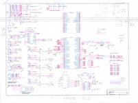
Don't really need a schematic, as far as the MCU interface to the PGA2311/PGA2310/PGA2320 parts.
I attached my example schematic.
To start with, I used a Sparkfun xmega100 BOB (Break Out Board) and the ole wire-warp sockets/wire/gun,soldering iron & parts. I used a standard 12VDC wall-wart,5V & 3V regs such as 78xx or 317 (not drawn on the schematic).
The rotary encoders work well!!
Okay will post the test schematic and can provide the code as well later if you want it. It is all xmega based so over kill for what you want to do as you described.
I used a PWM, using pin "PD0" to generate a signal to test the PGA2311 & PGA2310, both work at +/- 5V.
Four line LCD as indicated
A great learning tool!!
Mr. Mooly, Thread moved to Digital Line Level.
I searched for "PGA2311 & PGA2310/20" parts and found it in many forums, no big deal just a matter of interpretation. Suggest to create a forum called "Digital Audio" to separate "pure analog" from stuff like this, which has digital interfaces.Not sure what the diff is between "Digital Line Level" & "Digital Source", certain leads to a mixed bag of sorts!!
Cheers
Rick
Kulamario,
Post your schematic and code and i will review it for you.
Don't really need a schematic, as far as the MCU interface to the PGA2311/PGA2310/PGA2320 parts.
I attached my example schematic.
To start with, I used a Sparkfun xmega100 BOB (Break Out Board) and the ole wire-warp sockets/wire/gun,soldering iron & parts. I used a standard 12VDC wall-wart,5V & 3V regs such as 78xx or 317 (not drawn on the schematic).
The rotary encoders work well!!
Okay will post the test schematic and can provide the code as well later if you want it. It is all xmega based so over kill for what you want to do as you described.
I used a PWM, using pin "PD0" to generate a signal to test the PGA2311 & PGA2310, both work at +/- 5V.
Four line LCD as indicated
A great learning tool!!
Mr. Mooly, Thread moved to Digital Line Level.
I searched for "PGA2311 & PGA2310/20" parts and found it in many forums, no big deal just a matter of interpretation. Suggest to create a forum called "Digital Audio" to separate "pure analog" from stuff like this, which has digital interfaces.Not sure what the diff is between "Digital Line Level" & "Digital Source", certain leads to a mixed bag of sorts!!
Cheers
Rick
Attachments
Mr. Mooly, Thread moved to Digital Line Level.
I searched for "PGA2311 & PGA2310/20" parts and found it in many forums, no big deal just a matter of interpretation. Suggest to create a forum called "Digital Audio" to separate "pure analog" from stuff like this, which has digital interfaces.Not sure what the diff is between "Digital Line Level" & "Digital Source", certain leads to a mixed bag of sorts!!
Cheers
Rick
Hi there Rick,
Mr Mooly eh... you'll go far
 Correct salutation is so important don't you think.
Yes, it's really difficult to know sometimes what forum is most appropriate. There is just so much crossover now and as technology changes the distinctions become more blurred. The "everything else" forum ran a close second to this one
I'll put your thoughts to the team anyhow
I Checked the datasheet and have moved to analogue line level, as although the chip is digitally controled the input and output are both analogue. That is the signal remains analogue.
My thoughts on the difference between digital source and digital line level (and the same applied for analogue) are:
For me, Digital source is something like CD, DVD, DAT, MP3 or any form of music server. That is, anything that allows you to play back music from some form of digital storage.
Line level on the other hand is something like a DAC, digital volume control, DSP units, or anything with at least digital inputs or outputs (but possibly analog inputs or outputs) but cannot directly read digital media for playback purposes.
Tony.
- Status
- This old topic is closed. If you want to reopen this topic, contact a moderator using the "Report Post" button.
- Home
- Source & Line
- Analog Line Level
- PGA2320 and Atmega8 Bascom Source Code Problem