The JFET/JFET cascode originated with Geza Csanky (1963)
This is likely a good place to note that what Brad is referring to here is the work of Geza Csanky, working at Motorola in the early 1960's. His US patent 3,271,633 (filed Jan 29, 1963) shows a JFET/JFET combo (Fig 3) where an upper NFET cascodes a lower NFET. He also shows a JFET/NPN bipolar cascode (Fig 4). Both structures are highly effective at reducing output C and increasing output Z, and are just as viable today as they were in 1963.
Unfortunately, Csanky's work is not very widely credited, even though many have found one or another of the two original variants to be useful. And, so also are complementary cascodes: JFET/JFET with P devices, or a PFET/PNP bipolar cascode. These circuits can achieve gigohm levels of low frequency Z, and fractional pF levels of C, with only two active parts, and entirely self biased. The performance can be entirely comparable to that of the Baxandall-Shallow cascode http://www.diyaudio.com/forums/solid-state/25172-baxandall-super-pair-11.html, but with much greater simplicity.
I highly recommend folks looking into the Csanky scheme for good performance.
Walt Jung
BTW Walt Jung is working on presenting some history of JFET cascodes and has dug up some details on pioneers of the technique, so I shall say no more about the probable first uses of the technique. However, the principle is clearly along the lines of the first use of the bootstrapped cascode using bipolars by Aldridge; and the effectiveness in the FET case, besides the increase in low-frequency output impedance, is particularly due to the pumping of the output drain-gate displacement current back into the lower JFET source. This is only effective when there is substantial Z in the source compared to the reciprocal transconductance, so that most of the current flows in the source.
This is likely a good place to note that what Brad is referring to here is the work of Geza Csanky, working at Motorola in the early 1960's. His US patent 3,271,633 (filed Jan 29, 1963) shows a JFET/JFET combo (Fig 3) where an upper NFET cascodes a lower NFET. He also shows a JFET/NPN bipolar cascode (Fig 4). Both structures are highly effective at reducing output C and increasing output Z, and are just as viable today as they were in 1963.
Unfortunately, Csanky's work is not very widely credited, even though many have found one or another of the two original variants to be useful. And, so also are complementary cascodes: JFET/JFET with P devices, or a PFET/PNP bipolar cascode. These circuits can achieve gigohm levels of low frequency Z, and fractional pF levels of C, with only two active parts, and entirely self biased. The performance can be entirely comparable to that of the Baxandall-Shallow cascode http://www.diyaudio.com/forums/solid-state/25172-baxandall-super-pair-11.html, but with much greater simplicity.
I highly recommend folks looking into the Csanky scheme for good performance.
Walt Jung
Sorry that I missed your previous post.
I have been away from home and not checking frequently.
By coincidence, I tested the latest CCS version which was designed to lower thermal drift and reduce noise.
Today's test was only for DC drift.
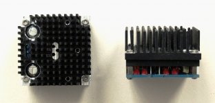
Apparently, even by using perfectly matched FETs and coupled them together using heat spreaders and heat sinks, it still drifts +/-20mV after 30 minutes.
Just touching the heat sink briefly by finger is sufficient to make a 10mV drift in seconds.
Just to show you how extremely sensitive JFETs are at µA level.
In that sense resistor and TL431 was less sensitive, though noiser.
More testing has to follow, but I think I want to keep the CCS version, at least for myself.
That means a servo has to be added, and we shall not release any project till they are tested to our own satisfaction.
While we appreciate your interest very much, I am afraid you will have a few months more to wait while we try to perfect this.
Patrick
I have been away from home and not checking frequently.
By coincidence, I tested the latest CCS version which was designed to lower thermal drift and reduce noise.
Today's test was only for DC drift.
Apparently, even by using perfectly matched FETs and coupled them together using heat spreaders and heat sinks, it still drifts +/-20mV after 30 minutes.
Just touching the heat sink briefly by finger is sufficient to make a 10mV drift in seconds.
Just to show you how extremely sensitive JFETs are at µA level.
In that sense resistor and TL431 was less sensitive, though noiser.
More testing has to follow, but I think I want to keep the CCS version, at least for myself.
That means a servo has to be added, and we shall not release any project till they are tested to our own satisfaction.
While we appreciate your interest very much, I am afraid you will have a few months more to wait while we try to perfect this.
Patrick
On the rare occasion I might be able to ask Walt a related question:
I modeled about every one or two device CCS I could think of as an educational exercise. Granted, I was limited to the various devices available in LTSpice. And oh boy, was the fet-fet stiff. But what I noticed as a trend, was their impedance varied considerably with frequency. The higher the impedance, the lower in frequency they degraded. By the model, in the 2 to 5K range which is not where we want things changing on us. I wonder, could this be a possible reason some prefer the simple resistor or BJT/LED? Though no where near as "constant", more consistent. Was my model's problem that I just did not have fast enough devices? ( I was using fairly high voltage parts as to be suitable in a power amp)
I have also wondered about the relationship between a ccs and having a well regulated supply. For a line stage, buffer etc, with a very good supply, what does the ccs really do for you?
One of my back burner projects is a clone MV-50 where I can swap out the IPS and VAS CCSs and see if I can actually hear a difference. It is going to take considerable work to make the outputs better than the inputs though.
I don't know if Walt is following this thread anymore (notice how old his post is), but if I may: you seem almost hopelessly hung up on this impedance with frequency thing being a problem. "Which is not where we want things changing on us." Why?? If the impedance is frightfully high, ANY stray capacitance will swamp out such changes completely. It does NOT translate into a problem for a VAS or much of anything else. If it still bothers you, shunt the damn thing with a resistor to flatten it.On the rare occasion I might be able to ask Walt a related question:
I modeled about every one or two device CCS I could think of as an educational exercise. Granted, I was limited to the various devices available in LTSpice. And oh boy, was the fet-fet stiff. But what I noticed as a trend, was their impedance varied considerably with frequency. The higher the impedance, the lower in frequency they degraded. By the model, in the 2 to 5K range which is not where we want things changing on us. I wonder, could this be a possible reason some prefer the simple resistor or BJT/LED? Though no where near as "constant", more consistent. Was my model's problem that I just did not have fast enough devices? ( I was using fairly high voltage parts as to be suitable in a power amp)
I have also wondered about the relationship between a ccs and having a well regulated supply. For a line stage, buffer etc, with a very good supply, what does the ccs really do for you?
One of my back burner projects is a clone MV-50 where I can swap out the IPS and VAS CCSs and see if I can actually hear a difference. It is going to take considerable work to make the outputs better than the inputs though.
BTW Walt's more detailed results are on his website, I believe including some things not shown anywhere else.
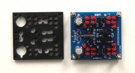
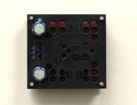
In: "going all the way", nobody beats you Patrick!Here a few pictures of the latest CCS version.
Maybe more grasping at straws for something in topology that relates to perceived sound quality. I had not heard a reason I am off the cliff on this. Good point, parastatics may swamp it. That's as good a reason as any. Might that suggest the ubiquitous BJT/LED is good enough for most standard applications.

Added complication, and some people swear they affect the sound .....
So I took the challenge to try to do without.
But as you also said before, doing it for circuits without global feedback is very tricky ....
Apparently the N and the P devices do not track each other very well thermally.
Patrick
So I took the challenge to try to do without.
But as you also said before, doing it for circuits without global feedback is very tricky ....
Apparently the N and the P devices do not track each other very well thermally.
Patrick
If you follow other threads I post, you would notice that I have a HAGS module (gain of 4) for the DAO SE headphone amp.
http://www.diyaudio.com/forums/head...ss-zgf-headphone-amplifier-2.html#post3436424
This has been proven to be DC stable even with gain of 4.
The circuit topology is very similar to that of the XCEN, so that I can see no reason why it cannot be adapted.
So at this moment, we'll finish th ework on the HAGS first before we come back to adapt the results there for the XCEN.
Patrick
- Home
- Source & Line
- Analog Line Level
- The XCEN -- Balanced to Single Ended Converter