We did a bit of shopping at digikey 
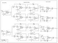
We bought some opa2134, (and some TL072 in sale, just in case). To power them, we bought a pair of ICL7660. They can give us 45mA -12V supply. If this isn't enough current, we will use a 2W DC/DC converter (12Vin, +/-9Vout, for 120mA). We'll make a standard Linkwitz-Riley2 way crossover. so we bought 0.1% tollerance resistors (7.5K and 15K) and 3% 4.7nF capacitors. We have designed an additional output buffer stage with variable gain (using 10K two-ganks potentiometers). Its intended to have a 5V/V gain at full throttle and 2.4 at minimum position. Attached, the simulated circuit.
Do you find any error in this?
We will then use 2 vu-meter IC at the output, to drive some green+red led (green lights at about 0.7V, red above1.4V) to prevent clipping.
What do you mean with decupling? Are you taling about decupling DC supplies? We are planning to insert 220uF electrolytic +100nF plastic in parallel for each op-amp. Will this be enough? .
Or are you talking about decupling DC component in the signal? We haven't planned to add more capacitors for this purpose, we are confident about the input stage of the amp boards, which won't be alterated for now.
By now, we have about 2x100W, 2x50W, 2x30W and some smaller solar cells.
We have planned a 12V rail for ta2024 (tweeters), crossover and miscellanea, and a bigger 30V rail for the big amp (bi-amped, bi-powered, sounds fine!). We have designed a standard supply regulator for both of them.. Two cells in series give about 40V, we will use some LM338 for 30V regulation and about 0.090F of capacitors for now. After some testing and some math we think that we should need about 1F or 2F for optimal performances at very max volume, in order to cover the current peaks. This would be more costy than buy more solar cells or batteries, and a bit dangerous for outdoor applications. We will use the system in this way for now and, depending of its performance, we will think about more electrolytic, batteries or other solutions if we'll found the necessity. Don't worry, it's quite loud anyway .
Btw, we don't want to play at night, there's not many outdoor places where is allowed to play music that loud after the sunset without bad side effects . We shall buy a large AC/DC power supply for indoor uses rather than a huge and useless rack of automotive SLAs
I tried to post in the boombinator's thread, but no one helped me, they we're saying that I should not talk about different design, 'cause this would be OT. I want to play louder than them, but that seems to not be interesting .
We bought some opa2134, (and some TL072 in sale, just in case). To power them, we bought a pair of ICL7660. They can give us 45mA -12V supply. If this isn't enough current, we will use a 2W DC/DC converter (12Vin, +/-9Vout, for 120mA). We'll make a standard Linkwitz-Riley2 way crossover. so we bought 0.1% tollerance resistors (7.5K and 15K) and 3% 4.7nF capacitors. We have designed an additional output buffer stage with variable gain (using 10K two-ganks potentiometers). Its intended to have a 5V/V gain at full throttle and 2.4 at minimum position. Attached, the simulated circuit.
Do you find any error in this?
We will then use 2 vu-meter IC at the output, to drive some green+red led (green lights at about 0.7V, red above1.4V) to prevent clipping.
Hi,
[...]
I think your idea of a small battery to cover if you want to play loud when there is a cloud is probably a good idea. As you pointed out if you want to party into the night you will need fairly large SLA (Solid lead acid) batteries then recharge them the next day but it sounds like this is not your plan.
There is also a good thread on the class D forum on solar boom boxes. Its not quite the same concept as yours as they seem to want to play all day and night! but there is lots of good ideas there.
http://www.diyaudio.com/forums/class-d/104402-boominator-another-stab-ultimate-party-machine.html
Regards,
Andrew
What do you mean with decupling? Are you taling about decupling DC supplies? We are planning to insert 220uF electrolytic +100nF plastic in parallel for each op-amp. Will this be enough? .
Or are you talking about decupling DC component in the signal? We haven't planned to add more capacitors for this purpose, we are confident about the input stage of the amp boards, which won't be alterated for now.
By now, we have about 2x100W, 2x50W, 2x30W and some smaller solar cells.
We have planned a 12V rail for ta2024 (tweeters), crossover and miscellanea, and a bigger 30V rail for the big amp (bi-amped, bi-powered, sounds fine!). We have designed a standard supply regulator for both of them.. Two cells in series give about 40V, we will use some LM338 for 30V regulation and about 0.090F of capacitors for now. After some testing and some math we think that we should need about 1F or 2F for optimal performances at very max volume, in order to cover the current peaks. This would be more costy than buy more solar cells or batteries, and a bit dangerous for outdoor applications. We will use the system in this way for now and, depending of its performance, we will think about more electrolytic, batteries or other solutions if we'll found the necessity. Don't worry, it's quite loud anyway
.Btw, we don't want to play at night, there's not many outdoor places where is allowed to play music that loud after the sunset without bad side effects
. We shall buy a large AC/DC power supply for indoor uses rather than a huge and useless rack of automotive SLAs I tried to post in the boombinator's thread, but no one helped me, they we're saying that I should not talk about different design, 'cause this would be OT.
I want to play louder than them, but that seems to not be interesting .Attachments
Hi, Each OPA2314 will require approx 5mA quiescent current per opamp (not per chip). So you can use 4 dual channel opamps chips in your design assuming the load current is negligible (which is likely if the input impedance of the power amplifier is fairly high).
I would think the 8 opamps in 4 chips should be enough to do your L-R filters and buffers. I estimate this should actually take 6 opamps (not dual chips) for a stereo system.
Decoupling is for the DC supplies, 220uF should do as bulk decoupling for all the opamps so long as you have 100nF close to each opamp. There is no need for 220uF on each opamp. (If interstage DC block capacitors are used these are called coupling capacitors, as you have indicated its unlikely you will need these)
Simulation looks OK. If you use OPA2134 the input offset bias current is so low you don't really need to worry about impedance matching between positive and negative inputs, but it won't hurt if you leave it in.
I'll be interested to hear how the amplifier holds up, the peak to mean ratio of music is quite high so even when playing loud the RMS power can be quite low. Worst case music is normally reckoned to have a peak to mean of about a factor of 8.
Regards,
Andrew
Hi, Each OPA2314 will require approx 5mA quiescent current per opamp (not per chip). So you can use 4 dual channel opamps chips in your design assuming the load current is negligible (which is likely if the input impedance of the power amplifier is fairly high).
I would think the 8 opamps in 4 chips should be enough to do your L-R filters and buffers. I estimate this should actually take 6 opamps (not dual chips) for a stereo system.
Decoupling is for the DC supplies, 220uF should do as bulk decoupling for all the opamps so long as you have 100nF close to each opamp. There is no need for 220uF on each opamp. (If interstage DC block capacitors are used these are called coupling capacitors, as you have indicated its unlikely you will need these)
Simulation looks OK. If you use OPA2134 the input offset bias current is so low you don't really need to worry about impedance matching between positive and negative inputs, but it won't hurt if you leave it in.
I'll be interested to hear how the amplifier holds up, the peak to mean ratio of music is quite high so even when playing loud the RMS power can be quite low. Worst case music is normally reckoned to have a peak to mean of about a factor of 8.
Regards,
Andrew
Thank you for your answers
For each channel (L/R):
input->buffer (1opamp)->HF and LF (4opamps)->output buffer(2opamp, one for HF, one for LF)
so each channels need 7opamps, that means 7x OPA2314 for the whole board.
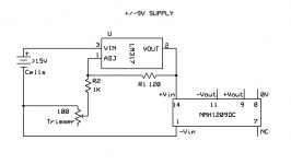
We now have some ICL7660S, the one with oscillator frequency boost (35KHz instead of 10K). If current is not enough, we can parallel a pair of them or use one for each channel. Btw, they will work at their max rated supply voltage (12V). original 7660 isn't even designed for such voltages.
We also have the NMH1209DC that seems really good, and can supply +/-111mA. Maybe an overkill? I'm quite sad 'cos according to datasheet, it seems to need an LC filter for best output ripple, and it's not easy to find a 47uH inductor now...I should have bought it from digikey
What design seems the best to you?
For decupling...lol, now i've got too many 220uf capacitors
. I'll use just one of them (will bigger capacitors work better or just a waste of space on the board?). 100nF will be as close as possible to every IC's Vin pin. they are also quite useful as jumpers, on a single layer pcb Playing a 0db sine wave at 0.8V rms on a tk2050 channel makes the amplifier put out about 12V on 4ohm. Full power (and 10%THD) can be obtained with a 1.5V rms signal. Under this condition, it gives about 30V rms on the 4ohm speaker, so about 100Wrms, and about 100W of supply power drained (never goes too much over 4A). It's very efficient, as intended!
Real music is obviously different. It's never recorded at 0db, standard commercial values are -10 and -6db. Newer music is highly compressed in dynamic, so this helps a bit. The real problem about audio peaks is that they are very long. Relatively to audio signals, they last forever! It's easy to cover voltage ripples, that are high-frequency noise (from eg a switching supply) with relatively small capacitors. But even assuming a reasonable peak/mean ratio, and a not-crap supply bench (like 2X mean power needing) ,in order to cover this "4A, tenth-of-second-long" peaks, we should need huge capacitors . But instead of spend $$$ for more and more farads, a more viable choice would be spending $ on power sources
Little mistake. output at full volume @4ohm is 21V, not 30VThank you for your answers
[...]
Full power (and 10%THD) can be obtained with a 1.5V rms signal. Under this condition, it gives about 30V rms on the 4ohm speaker, so about 100Wrms [...]
I haven't used either of the voltage inverters you have listed but the NMH1209DC looks like it will probably give you a better result as it has built in magnetics and is transformer based (providing a better isolation from the main supply) rather than capacitor based.
Bigger capacitors just after the voltage inverter should help by providing a low impedance bulk storage to swamp the output impedance of the inverter.
You need to be a bit more carefull with capacitors in the audio circuits as you can just end up coupling noise from the power supplies into the ground return path. Hence it is probably better to just use one set of bulk decoupling capacitors near the opamps. You could use separate bulk caps for the for the H.F and L.F stages depending on how you route them just try not to mix the H.F and L.F ground return paths.
Regards,
Andrew
I haven't used either of the voltage inverters you have listed but the NMH1209DC looks like it will probably give you a better result as it has built in magnetics and is transformer based (providing a better isolation from the main supply) rather than capacitor based.
Bigger capacitors just after the voltage inverter should help by providing a low impedance bulk storage to swamp the output impedance of the inverter.
You need to be a bit more carefull with capacitors in the audio circuits as you can just end up coupling noise from the power supplies into the ground return path. Hence it is probably better to just use one set of bulk decoupling capacitors near the opamps. You could use separate bulk caps for the for the H.F and L.F stages depending on how you route them just try not to mix the H.F and L.F ground return paths.
Regards,
Andrew
I didn't found 47uH inductors near my place. We won't implement this filters for now, but we'll design the pcb to implement them in the future. For now, a 200uf bulk capacitor will be the way. (i've got some small 1000uF 16V capacitors, would be better o worse?).
For now, I'm not too worry about supply noises. Power is coming from solar cells and reulated, so there's no much AC components in it.
I think it won't be easy to design the pcb with all these requirements. Do you have some similar PCB design that I could look at? Any examples of good designs?
Now, it's a shame but i have to ask, 'cos i've not experience about this:
The ouptut of each channel's LF will be splitted in two, because a single LF signal will drive 2 tk2050's channels.
I've not designed something particular. Actually, the split happens after the output buffer.
So what appens after this split?
Vrms remain the same, and just the current drained doubles (in this case, will the crossover have some troubles)?
Or the split will cause Vrms attenuation, and we'll need more gain to compensate?
Or should we make an output buffer for every single output (I hope we shouldn't).
Input impedance is about 20Kohm for every tk2050 in, same value fot the little sister's inputs.
Hi, for the split the current doubles, opamps are voltage output devices. If the input impedance of power amplifier is 20k then the approx 10k load will be no problem for the opamp in your buffer circuit.
I am not sure if I have any example boards, most of my work has been on commercial designs and normally on 2 layers or more. Single sided layouts are difficult to get working well. I'll have a look and see if I can find anything.
Andrew
I am not sure if I have any example boards, most of my work has been on commercial designs and normally on 2 layers or more. Single sided layouts are difficult to get working well. I'll have a look and see if I can find anything.
Andrew
I haven't found any good examples of single sided boards however this guide may be of some help.
http://alternatezone.com/electronics/files/PCBDesignTutorialRevA.pdf
1000uF on 9v rails would be a good bulk decoupler after the inverter / regulator.
Regards,
Andrew
http://alternatezone.com/electronics/files/PCBDesignTutorialRevA.pdf
1000uF on 9v rails would be a good bulk decoupler after the inverter / regulator.
Regards,
Andrew
Testing Time!
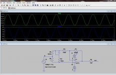
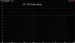
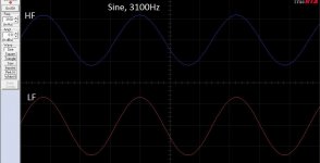
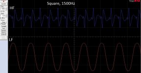
So, we did the schematic for the crossover network and for the dual supply rail, and tested the whole thing on a breadboard (excluding the variable gain output buffer stage).
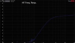
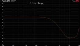
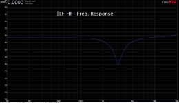
We've not listened at it yet, but we did some measurements. Everything seems just fine! Measurement system is not the best, but seems to do its job: laptop with TrueRTA using a TASCAM US-144 as aq. board. (note: very high frequency response in the LF's plot are reasonably altered by wrong system's self-calibration)
I'm quite impressed, it seems to be better than what I expected!
We used no particoular decupling, just 100nF near to each opamp's supply rails. No electrolytics are in the circuit.
Thank you a lot... just 2 more questions:
So, we did the schematic for the crossover network and for the dual supply rail, and tested the whole thing on a breadboard (excluding the variable gain output buffer stage).
We've not listened at it yet, but we did some measurements. Everything seems just fine! Measurement system is not the best, but seems to do its job: laptop with TrueRTA using a TASCAM US-144 as aq. board. (note: very high frequency response in the LF's plot are reasonably altered by wrong system's self-calibration)
I'm quite impressed, it seems to be better than what I expected!
We used no particoular decupling, just 100nF near to each opamp's supply rails. No electrolytics are in the circuit.
1000uF on 9v rails would be a good bulk decoupler after the inverter / regulator.
Regards,
Andrew
Thank you a lot... just 2 more questions:
- I read at page 8 of this sheet that i shouldn't use >100uF capacitors after the DCDC converter:
So...what suould I do?A simple method of reducing the output ripple is simply to add a large external capacitor. This can be a low cost alternative to the LC filter approach, although not as effective. There is also the possibility of causing start up problems, if the output capacitance is too large.With a large output capacitance at switch on, there is no charge on the capacitors and the DC-DC converter immediately experiences a large current demand at its output. The inrush current can be so large as to exceed the ability of the DC-DC converter, and the device can go into current limit or an undefined mode of operation. In the worst case scenario the device continuously "hiccups" as it tries to start, goes into overload shutdown and then retries again. The DC-DC converter may not survive if this condition persists. For the Powerline the maximum capacitive loads are specified. For Econoline please refer to the tables below. - At the moment we have several "gound point": one from solar cells, one from the DC converter "0V" pin, and one (two) coming from stereo input, and from outputs too. Now, they are all connected together and everything seems to work fine. Is this the right layout, or should I do that in some other way?
Attachments
Hi,
Sorry I as I said I have not used this part and I didn't read the data sheet very carefully. If its not designed to run into large caps then just use the 100uF suggested. (If you want to use your 220uF parts since you have already bought them 2 in series will give you 110uF which is close enough). It won't have such a good transient response but the opamps shouldn't draw that much current so the 100uF will be OK.
It sounds like you have formed an approximate star ground (i.e. all the grounds connected together in one point) if this is working well stick with it, it is one of the easiest grounding schemes to get working.
Results look good, but keep in mind it is very unlikely that your speakers will have a flat response around your crossover point. Whilst this schematic is a good starting point if you want it to sound well integrated you will need to take acoustic measurements and optimise the electronics to match the acoustic roll off of your drive units.
For this you will need a measurement microphone. So long as you have a fairly good sound card a very acceptable measurement microphone cab be made for about 5 euros (much less if you can get the capsule at trade price) using the WM61A mic cartridge from Panasonic and the outside of a plastic biro to hold it. It is flat enough to measure the crossover region and optimise it. See this site for more information (you don't need the pre-amplifier if you are using a PC sound card)
http://www.johncon.com/john/wm61
a/
I use Holm impulse software with mine which is a good free maximum length sequence system analyser that works with most computer sound cards.
HOLM Acoustics
The advantage of this type of measurement is that at above about 400Hz you can modify the impulse response by cutting of the end and remove room reflections so you get an anechoic like measurement in any room so long as you don't need the low frequency information.
Regards,
Andrew
Last edited:
Hi,
Sorry I as I said I have not used this part and I didn't read the data sheet very carefully. If its not designed to run into large caps then just use the 100uF suggested. (If you want to use your 220uF parts since you have already bought them 2 in series will give you 110uF which is close enough). It won't have such a good transient response but the opamps shouldn't draw that much current so the 100uF will be OK.
It sounds like you have formed an approximate star ground (i.e. all the grounds connected together in one point) if this is working well stick with it, it is one of the easiest grounding schemes to get working.
Results look good, but keep in mind it is very unlikely that your speakers will have a flat response around your crossover point. Whilst this schematic is a good starting point if you want it to sound well integrated you will need to take acoustic measurements and optimise the electronics to match the acoustic roll off of your drive units.
For this you will need a measurement microphone. So long as you have a fairly good sound card a very acceptable measurement microphone cab be made for about 5 euros (much less if you can get the capsule at trade price) using the WM61A mic cartridge from Panasonic and the outside of a plastic biro to hold it. It is flat enough to measure the crossover region and optimise it. See this site for more information (you don't need the pre-amplifier if you are using a PC sound card)
[...]
That warning wasn't on murata's datasheet (wich is quite useless), it's referring other's DCDC converter, but i think it's a reasonable advice. According to murata's application hints, there aren't no capacitors except from the 2.2nF of the LC filter. I think that's because it's unregulated, and it's intended to be used before the DC/DC, directly to the regulator.
We have plenty of electrolytics, so we don't care about finding other values like 100uF (or have 10 more 220uF caps in the lab
)With this star ground all seems to work fine with a lab bench supply, ad it will be better with the real application (powered via solar cells or batteries). I'm just worried because eventually we'll get a switching power supply for indoor uses, and this could introduce some noise whith such a ground loop. I'll have care to make connection between grounds only via jumpers, so we can tweak the whole thing later.
Actually, the cutoff frequency is very close to the reccomend one directly from ciare's project. And we simulated the filter with some softwares, and the system sounded pretty fine. HF and LF levels can be regulated indipendently, and frequency tweaks cannot be made without desoldering everything.
I'm looking for a good microphone for other projects, and maybe we'll get it soon (maybe for more than 5$). thanks for the precious infos, but we think that we'll use the crossover in this way. It would be great just if doesn't output distorsion or noises
The real challenge now is the PCB design. I did some little projects before, but this is quite big network. I've always used ExpressPCB. Do you suggest some other software?
Last edited:
We made it! It was hard to fit the whole circuits on a single sided 10x15 cm board. In addition, we had troubles with the old "toner method" used to print the pcb and it ended with half of the traces made by hand, but we did it. The crossover works flawlessly. It's a bit noisy, but it's just a white noise on the backgound, no hums and ripples , and it can't be noticed when playing music, even at low volumes.
Now we'll make a smaller board with digital vu meters and signal splitters to feed the amplifiers (this things didn't fit on the same board in any way I tried).
Now i'm working on the power regulator, i'm looking for the right design. I think I'll cross-post
Now we'll make a smaller board with digital vu meters and signal splitters to feed the amplifiers (this things didn't fit on the same board in any way I tried).
Now i'm working on the power regulator, i'm looking for the right design. I think I'll cross-post
- Status
- This old topic is closed. If you want to reopen this topic, contact a moderator using the "Report Post" button.
- Home
- Source & Line
- Analog Line Level
- HELP! line-level crossover design for solar-powered biamped soundsystem