I have one SE 2A3 tube amp with an input sensitivity of about 4v p-p to clip that would benefit from a slight amount of voltage gain but, this was not my primary purpose for this preamp...i am building a pair of NAP140 clone monoblocks and I wanted a preamp to run them that worked from SLA batteriies (just wanted to try a preamp with SLA power source).
So, not absolutely necessary but if one with a minimal amount of gain were available, that would be beneficial....
So, not absolutely necessary but if one with a minimal amount of gain were available, that would be beneficial....
The B1 draws an average current equal to the Idss of the jFETs selected. This could be as low as 6mA (for two channels) but more likely to be in the range 12mA to 18mA (for stereo).
So, will it run on 12v +/- rails?
Discrete high performance linestage design with 12v rails
jmillerdoc,
Here is a very high performance balanced input linestage designed for a bipolar 12 volt supply. Low distortion - 0.000082% THD. Can be used single ended too, just tie either input to common. Output will remain the same regardless balanced or single ended.
I provided an LTSpice file of it if you are so inclined.
Enjoy...
Best Regards,
Rich
Attachments
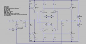
Awesome...i am not too familiar with this type of schematic. Can you help me with a few small details? The input seems to be on the left side...what is that circle with the +/- inside it? Also, how os the output wired? One side of the "load" resistor is output and the other groind? Can you please explain it a little better for me? I dont know how to convert this into a wiring diagram....
So, for unbalanced input i could essentially eliminate the (-) leg of the schematic and its associated resistorS R20 and R15? and make my input between resistors R19 and R12 and ground? Am I reading this correctly...that would essentially be the same thing as tying the (-) pole of the balanced inout to ground right?
Not much experience in matching transistors...is there an easy way to do this with minimal electronic equipment? I.e. DVM, power supply....? Or, is there a substitute transistor one of the various members here sells matched?
Not much experience in matching transistors...is there an easy way to do this with minimal electronic equipment? I.e. DVM, power supply....? Or, is there a substitute transistor one of the various members here sells matched?
Discrete high performance linestage design with 12v rails
Jmillerdoc,
Sorry I couldn’t return to your questions sooner.
The circle with +/- inside is called an “Independent Voltage Source”. It is one of the many tools available to a circuit designer within LTSpice. I utilized it as a signal source.
The output is represented by “LOAD”. LTSpice requires the input and output to be referenced to supply common (return, ground, etc.).
AndrewT,
Sorry, you cannot make this circuit with a balanced output by “duplicating Q7&8 and feeding them from the two unused collector resistors R9&11. Will not work.
Therefore,
I utilized complementary 500ma transistors in the first model for a couple reasons.
See if anyone actually notices and furthermore to spur additional discussion.
Demonstrate just how flexible the circuit actually is.
Is it practical to make it with those devices? Depends upon the individual and what it will be used for.
In general, perhaps a more practical choice can be any of the following.
BD139, BD140
2N2222, 2N2907
2N3905, 2N3906
2N4401R, 2N4403
MPSA05, MPSA055
MPS8099, MPS8599
BC546B, BC556B
BC547C, BC557C
BC550, BC560
But then actually, any average “complementary rated” pair will work just fine. Most modern versions (1995 and later) will not require to be matched to obtain exceptionally good results. Of course you are ultimately at liberty to get as exotic as you desire, although so will the expense.
This circuit was a workhorse that was developed and utilized throughout a lot of pro-sound equipment I made starting in the mid 70’s. It was an era when commercial gear first became integrated with op-amps. A lot of that equipment possessed many disadvantages that I won’t get into here.
I sought very high performance together with flexibility, dependability and ease of repair if ever required. Performance liability was a significant factor. It works well with higher supply voltages and merely slight modification too.
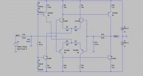
I attached another schematic that hopefully you find more comprehensible.
Enjoy.
Best Regards,
Rich
Jmillerdoc,
Sorry I couldn’t return to your questions sooner.
The circle with +/- inside is called an “Independent Voltage Source”. It is one of the many tools available to a circuit designer within LTSpice. I utilized it as a signal source.
The output is represented by “LOAD”. LTSpice requires the input and output to be referenced to supply common (return, ground, etc.).
AndrewT,
Sorry, you cannot make this circuit with a balanced output by “duplicating Q7&8 and feeding them from the two unused collector resistors R9&11. Will not work.
Therefore,
I utilized complementary 500ma transistors in the first model for a couple reasons.
See if anyone actually notices and furthermore to spur additional discussion.
Demonstrate just how flexible the circuit actually is.
Is it practical to make it with those devices? Depends upon the individual and what it will be used for.
In general, perhaps a more practical choice can be any of the following.
BD139, BD140
2N2222, 2N2907
2N3905, 2N3906
2N4401R, 2N4403
MPSA05, MPSA055
MPS8099, MPS8599
BC546B, BC556B
BC547C, BC557C
BC550, BC560
But then actually, any average “complementary rated” pair will work just fine. Most modern versions (1995 and later) will not require to be matched to obtain exceptionally good results. Of course you are ultimately at liberty to get as exotic as you desire, although so will the expense.
This circuit was a workhorse that was developed and utilized throughout a lot of pro-sound equipment I made starting in the mid 70’s. It was an era when commercial gear first became integrated with op-amps. A lot of that equipment possessed many disadvantages that I won’t get into here.
I sought very high performance together with flexibility, dependability and ease of repair if ever required. Performance liability was a significant factor. It works well with higher supply voltages and merely slight modification too.
I attached another schematic that hopefully you find more comprehensible.
Enjoy.
Best Regards,
Rich
Attachments
I just purchased 30 pairs of the transistors you specified from an eBay source for $4. So, no matching required then, that makes it easier.
If I wanted to use the Salas shunt regulator for this, what would the best output in mA be for the regulator?
I was wondering if it would be very expensive to have some PCBs made for this little project? I know this can be done, anyone here know the cheapest place to have a few PCBs made? Someplace I could just send them this diagram and have them pop a few out for a reasonable cost....if I had to make several i would even be willing to do that and sell off the additional at cost if there was interest.
I found PCBexpress online and sent them an inquiry about producing several of these...i want a single channel on a single PCB and specified through hole 1/4w resistors for size sake. Waiting for a response and a price. If anyone wants a pair I would be willing to add a few to my order.
Discrete high performance linestage design with 12v rails
Jmillerdoc,
As is, each circuit load will be about 2.8ma per supply leg. This is a Class A design that will not increase demand regardless of reasonable load. It can easily drive a 1k ohm load.
Of course you would not want to have your supply so limited. 20 to 30ma per supply leg is all that is needed.
As far as recommend a good pc board company, most are more interested in more than just making a few boards.
I think some DIY members make boards. Post a request and see who might be interested.
Best Regards,
Rich
PCBexpress is insane...they would want about $50 a board with a 10pc purchase...around $500....no way! I would etch my own before considering that.
Check out PCB Power (India) Ltd. - I have no interest in it, except as a delighted customer. They do prototype quantities at competitive rates using pooled services, but they also have Express and On-Demand services with more finish options, etc.
Welcome to PCBPower.com
You'll have to register and get verified by their customer service before you can place an order, but you can do price calculations based on board dimensions and options without registration. Once registered and verified, almost everything can be transacted using the web interface, including invoices and payments.
Regarding a high-performance line stage, I have prototypes of several different discrete Class-A opamp modules:
Hybrid/discrete Class-A single opamp, DIP8:
http://www.diyaudio.com/forums/analog-line-level/193768-ann-lf01-discrete-hybrid-opamp-module.html
Fully discrete Class-A dual opamp, DIP8:
http://www.diyaudio.com/forums/analog-line-level/207871-lf03-discrete-opamp.html
The LF01 can use just about any SOIC8 single opamp, like the LT1028 or OPA627AU or similar. The LF03 is fully discrete, and still a bit experimental. There's also an LF02, which is basically a dual LF01, and uses any SOIC8 dual opamp.
PM me if there's any interest in bare PCBs and/or kits.
are you sure?you cannot make this circuit with a balanced output by “duplicating Q7&8 and feeding them from the two unused collector resistors R9&11. Will not work.
Flip the schematic left to right.
The new positions for the two extra output devices are now on the left.
Those give the other half of the balanced output.
This was a balanced in to balanced out schematic, until the four output devices were reduced to just two.
Discrete high performance linestage design with 12v rails
AndrewT,
Very sorry, although I am at a total loss trying to comprehend both your suggestions as well as your comment “this was a balanced in to balanced out schematic, until the four output devices were reduced to just two.”
As far as your suggestion describing how to create a balanced output out of it, at least what I think you are saying, no matter how I can imagine, would force quite a DC offset into both outputs, not to mention cause tremendous distortion.
Furthermore, your comment that this was some other prior schematic is not warranted simply because it isn’t part of any prior schematic. I did not modify it, changed it, or whatever, from any existing circuit at the time.
Can you please post a schematic diagram of your idea or at least the one you refer to that was “reduced”?
Rich
- Status
- This old topic is closed. If you want to reopen this topic, contact a moderator using the "Report Post" button.
- Home
- Source & Line
- Analog Line Level
- Looking for discrete high performance linestage design with 12v rails