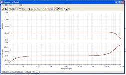
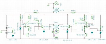
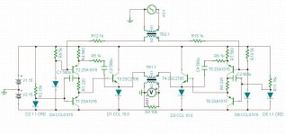
So, I'm putting this out there for comments. It's a simple circuit really, with a pair of 2SA1015's in SRPP formation driving an emitter follower on each side of the bridge. Feedback is taken from the emitter follower back to the emitter of the SRPP. I used ideal transformers in the sim because I wanted to know what the circuit was going to do. Obviously, performance will be much worse with real world transformers, which I already have (Jensen). I can't see anything wrong with this circuit so I want to build it but thought I'd post it first just to double check. I hope I didn't make any obvious errors. The only down side so far is that the input impedance is a bit low at 6k ohms.
I've tried different transistors and other arrangements but for 6dB of gain, this is just fine apparently. Performance seems to be really great.
I've tried different transistors and other arrangements but for 6dB of gain, this is just fine apparently. Performance seems to be really great.
Attachments
Dirk, I was just looking at that.
Another option is to put a resistor between the bias string (top of the diode) to the b of the Q.
Not sure which is more stable - your lean current (which decreases stability of the ref voltage with T) or a series R (which causes some T dependence too).
jan didden
Another option is to put a resistor between the bias string (top of the diode) to the b of the Q.
Not sure which is more stable - your lean current (which decreases stability of the ref voltage with T) or a series R (which causes some T dependence too).
jan didden
Dirk, I was just looking at that.
Another option is to put a resistor between the bias string (top of the diode) to the b of the Q.
Not sure which is more stable - your lean current (which decreases stability of the ref voltage with T) or a series R (which causes some T dependence too).
jan didden
thanks for the advice! much appreciated!
I lowed the current of the bias divider to a bit less than 500uA and increased the resistor to 5k. The circuit sims almost exactly the same, but of course this may be different in real life.
Attachments
I believe the 5k then sets the input Z. The real one will be lower because the dynamic impedance of the diode will be in parallel.
Or is it a current reg diode?
That's probably the best solution - an LM334 (?) current diode, that will work fine with only a few 100uA.
jan
They are all current regulating diodes (CRD, CLD, CCD, etc). They are expensive, but they make circuit design more simple for me.
- Status
- This old topic is closed. If you want to reopen this topic, contact a moderator using the "Report Post" button.