Introduction
For quite some time I have used an Aikido amplifier (6SN7, Jensen output caps). It is really straightforward, has a nice bandwidth and a good sound for popular and rock music. It works well with my 300B amplifier.
However, I found the Aikido to lack when using my F5 amplifier. At least I found it to deteriorate slowly slowly over time. I blame it for sometimes blocking complex sounds in classical music. At times it makes violins harsh and lets sopranos and choirs oversing. I am forced at such moments to reduce the volume. The problem could be due to a slew rate limiting of the 6SN7 tubes in the Aikido, that I had running at 180V.
I had a chance to listen to an audition set of Guido Tent in Eindhoven NL with his b-DAC and Bruno’s Hypex modules. A very natural soundstage, just the recording, no extra’s. What I liked a lot was that the digital potmeter gave the same sound stage independent of the volume setting. Very very nice effect. Something certainly to strive for. The Aikido certainly could not match that level of sophistication: it might be due to the fact that the HF roll-off shifts due to the changes of input resistance.
In the mean time I repaired a Yamaha Natural Sound CA-1000 amplifier and listened to its line stage. Impressive. Man, do I like that sound! But the whole amplifier, now 30 years old, cracks on all sides.
So, having some good examples in front of me - I started to look around for an alternative. I considered the Conrad Johnson, McIntosh C22 and Dynakit designs. I also found the Audio Research SP-6 that differs in the fact that the output is more tightly coupled to the input with one capacitor less in the circuit.
I looked at the DHT preamp too – but decided to do that later.
Several years back I made a set based on the Audio Research SP-6 circuit, using ECC82's. It worked fine but I settled for something else at that time: I dumped it in favor of a 6J6/E90CC amplifier that only had 12dB of feedback. A winner apart from the microphonics of the input, the reason I discarded it after 15 years of use in favor of the Aikido.
• Original SP-6 line stage:
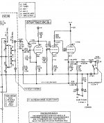
So I reverted back to the concept of the Audio Research SP-6 line stage. I redesigned it to amplify just 12,5 dB instead of 26,4 dB.
So how did the build go?
For quite some time I have used an Aikido amplifier (6SN7, Jensen output caps). It is really straightforward, has a nice bandwidth and a good sound for popular and rock music. It works well with my 300B amplifier.
However, I found the Aikido to lack when using my F5 amplifier. At least I found it to deteriorate slowly slowly over time. I blame it for sometimes blocking complex sounds in classical music. At times it makes violins harsh and lets sopranos and choirs oversing. I am forced at such moments to reduce the volume. The problem could be due to a slew rate limiting of the 6SN7 tubes in the Aikido, that I had running at 180V.
I had a chance to listen to an audition set of Guido Tent in Eindhoven NL with his b-DAC and Bruno’s Hypex modules. A very natural soundstage, just the recording, no extra’s. What I liked a lot was that the digital potmeter gave the same sound stage independent of the volume setting. Very very nice effect. Something certainly to strive for. The Aikido certainly could not match that level of sophistication: it might be due to the fact that the HF roll-off shifts due to the changes of input resistance.
In the mean time I repaired a Yamaha Natural Sound CA-1000 amplifier and listened to its line stage. Impressive. Man, do I like that sound! But the whole amplifier, now 30 years old, cracks on all sides.
So, having some good examples in front of me - I started to look around for an alternative. I considered the Conrad Johnson, McIntosh C22 and Dynakit designs. I also found the Audio Research SP-6 that differs in the fact that the output is more tightly coupled to the input with one capacitor less in the circuit.
I looked at the DHT preamp too – but decided to do that later.
Several years back I made a set based on the Audio Research SP-6 circuit, using ECC82's. It worked fine but I settled for something else at that time: I dumped it in favor of a 6J6/E90CC amplifier that only had 12dB of feedback. A winner apart from the microphonics of the input, the reason I discarded it after 15 years of use in favor of the Aikido.
• Original SP-6 line stage:

So I reverted back to the concept of the Audio Research SP-6 line stage. I redesigned it to amplify just 12,5 dB instead of 26,4 dB.
So how did the build go?
The basic SP-6 circuit.
The basic topology of the SP-6 has two stages and an output buffer. In contrast to other circuits, there is a DC feedback from the output to the first stage. All others have a DC-blocking capacitor in between. This is a secret of the circuit.
What can be improved or tweaked?
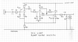
Final SP-6 ECC801S Light schema
Components
C1 - Input: 0,47 Westcap PIO or 154 nF Styroflex.
C2 - Coupling cap: 100nF 400V or 220 nF 250V I choose Philips MKC.
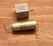
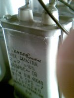
C3 - Output: 2 muF 600V Jensen paper in oil. Take the best you can find. High voltage rating.
C4*: input trimmer 4-20 pF ceramic, trim for best square wave. (discarded in final version)
C5*: Feedback cap. Originally tried 18 pF 250V styroflex for a 250 kHz roll off. (discarded in final version)
R1 - Stopper resistor : 820 ohms, carbon film, low inductance.
R2, R5 - Grid leakage: Dale 1M
R3 - Anode resistor: 94k. Needs to be low noise.
R4 - Cathode resistor: 2k2, metalfilm, low noise
R6, R9 – grid stoppers 1k2 to 1k5 non inductive Allan Bradley.
R7 - Anode resistor second stage: 51k Dale 2W
R8 - Cathode resistor second stage: 820 ohm, metalfilm
R10 - Feedback: 33k 5W Allan Bradley pressed carbon
R11 - 10 k metalfilm 2W. Can be changed to get desired amplification.
R12 - output damper: 300 ohms, Dale 1 W
R13 – 100k earthing
R14 – optional positive feedback, 330k
T1 - ECC801S. Long life version and gold pins.
T2 - ECC801S
T3 - Output Buffer high mu: PCC88 or ECC88 only use section 1 (pins 1/2/3). PCC88 is similar to ECC88 but has a higher heater voltage and a higher Vfk. A PCC88 or ECC88 (like PCC186 and similar) has two unequal halves. The sections differ in the max Vfk: the filament to cathode voltage. ECC88 section with pins 1/2/3 was designed to be the top of a cascode with a Vfk of 150V; the section with pins 6/7/8 are designed for the input of a cascode with a low Vfk voltage at 50V. So I use section with pins 1/2/3 only as buffer.
D1 – 1N4001 pass diode for start-up. In the SP-8 Audio Research did not use a diode but a JFET connected in a special way: S+D to grid, gate to cathode. Might be a sonic improvement.
M1: mute circuit 2k, IRF640 drives a relay. Delay 10 sec.
The C2 coupling cap has a big impact. Various types differ in the amount of ringing in the ultra high frequency range. Take a small type. A small size to fit on the socket itself.
The R3/R7 anode loads have to be good, low noise. I use 5 watt carbon resistors. But I might settle for even better WW
The R10/R11 resistors in the feedback (43k or 33k/10k) made a difference, but layout issues I found out about later made me aware of stray capacitances in this design – touching a component brought some ringing or damped the square wave. I like non-inductive types here as they set the poles directly.
With R14 I tried the positive feedback. With a 330 k resistor from the output to the cathode of the second stage, the open loop bandwidth lowered from 62 kHz to 55 kHz. I also tested this option with the distortion meter. Distortion rose a bit! In circuits like McIntosh C22 and Hiraga RIAA it is 330k, although the output buffer is at 200 volts in those designs. I did not seek an optimal value for the feedback resistor, I just left it with the value of 330k and a cathode load of 820ohm like in the C22.
I initially had a styroflex capacitor on the input, 63 volts, 153 nF, enough to give <2 Hz low end bandwidth. I later used 0,47 muF. It could be the Westcap is slightly bright.
The basic topology of the SP-6 has two stages and an output buffer. In contrast to other circuits, there is a DC feedback from the output to the first stage. All others have a DC-blocking capacitor in between. This is a secret of the circuit.
What can be improved or tweaked?
- First of all the stock SP-6 amplification is quite high, 26 dB (100k/5k). We nowadays like a lower one, like 15 dB.
- It runs on an unhealthy 420 Volts (jach) and needs a lot of regulation. Too much for me. I decided to use 250V max (because the existing HV PS of my Aikido already had that). But I want to keep the high output of > 20V RMS at < 0,02%. I like a high driveabiliy – a DAC can provide max 2,2 V RMS but a RIAA preamp can surpass that easily. The F5 with its +15 dB needs this high drive.
- The output impedance is rather high, even with all the feedback (100k current source).
- The coupling between the two stages makes a difference. The C22 used something like 22nF here and Hiraga 33nF in his RIAA instead of the stock 220nF. It influences the low end.
- The RIAA stage has a 20 pF cap between anode and grid; the line stage does without. With all the feedback and inherent this component is essential.
- And the stop resistor (1k8) in the stock line stage needed an experimental review of the value because of the trim cap I added.
- The grid to cathode cap of 20pF is part of the design; I wanted to see if it has impact.
- Some designs like the McIntosh C22 have a positive feedback to the second stage. It is claimed to give higher dynamics. I decided to test that too. It does of course decrease the anode current and increases the output DC level.
- The ECC83 has too high an amplification, so there is need for lower mu tubes like the ECC81 or even ECC82.
Final SP-6 ECC801S Light schema

Components
C1 - Input: 0,47 Westcap PIO or 154 nF Styroflex.
C2 - Coupling cap: 100nF 400V or 220 nF 250V I choose Philips MKC.
C3 - Output: 2 muF 600V Jensen paper in oil. Take the best you can find. High voltage rating.
C4*: input trimmer 4-20 pF ceramic, trim for best square wave. (discarded in final version)
C5*: Feedback cap. Originally tried 18 pF 250V styroflex for a 250 kHz roll off. (discarded in final version)
R1 - Stopper resistor : 820 ohms, carbon film, low inductance.
R2, R5 - Grid leakage: Dale 1M
R3 - Anode resistor: 94k. Needs to be low noise.
R4 - Cathode resistor: 2k2, metalfilm, low noise
R6, R9 – grid stoppers 1k2 to 1k5 non inductive Allan Bradley.
R7 - Anode resistor second stage: 51k Dale 2W
R8 - Cathode resistor second stage: 820 ohm, metalfilm
R10 - Feedback: 33k 5W Allan Bradley pressed carbon
R11 - 10 k metalfilm 2W. Can be changed to get desired amplification.
R12 - output damper: 300 ohms, Dale 1 W
R13 – 100k earthing
R14 – optional positive feedback, 330k
T1 - ECC801S. Long life version and gold pins.
T2 - ECC801S
T3 - Output Buffer high mu: PCC88 or ECC88 only use section 1 (pins 1/2/3). PCC88 is similar to ECC88 but has a higher heater voltage and a higher Vfk. A PCC88 or ECC88 (like PCC186 and similar) has two unequal halves. The sections differ in the max Vfk: the filament to cathode voltage. ECC88 section with pins 1/2/3 was designed to be the top of a cascode with a Vfk of 150V; the section with pins 6/7/8 are designed for the input of a cascode with a low Vfk voltage at 50V. So I use section with pins 1/2/3 only as buffer.
D1 – 1N4001 pass diode for start-up. In the SP-8 Audio Research did not use a diode but a JFET connected in a special way: S+D to grid, gate to cathode. Might be a sonic improvement.
M1: mute circuit 2k, IRF640 drives a relay. Delay 10 sec.
The C2 coupling cap has a big impact. Various types differ in the amount of ringing in the ultra high frequency range. Take a small type. A small size to fit on the socket itself.
The R3/R7 anode loads have to be good, low noise. I use 5 watt carbon resistors. But I might settle for even better WW
The R10/R11 resistors in the feedback (43k or 33k/10k) made a difference, but layout issues I found out about later made me aware of stray capacitances in this design – touching a component brought some ringing or damped the square wave. I like non-inductive types here as they set the poles directly.
With R14 I tried the positive feedback. With a 330 k resistor from the output to the cathode of the second stage, the open loop bandwidth lowered from 62 kHz to 55 kHz. I also tested this option with the distortion meter. Distortion rose a bit! In circuits like McIntosh C22 and Hiraga RIAA it is 330k, although the output buffer is at 200 volts in those designs. I did not seek an optimal value for the feedback resistor, I just left it with the value of 330k and a cathode load of 820ohm like in the C22.
I initially had a styroflex capacitor on the input, 63 volts, 153 nF, enough to give <2 Hz low end bandwidth. I later used 0,47 muF. It could be the Westcap is slightly bright.
some measureements and listening experiences
SP-6 Light Specs:
bandwidth from <2 Hz to >150 KHz, flat (less than 0,5 dB).
20V RMS output possible, fast rise time.
12,5 dB amplification.
Distortion: less than 0,01 %
Noise level: not measurable. And not audible, no hum.
Bandwidth stays rather constant with a potmeter of 50k: a very good sign. This implies the sonic signature stays constant (unlike other topologies!).
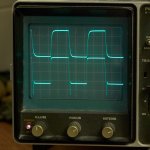
Square wave 53 kHz with 18 pF feedback (top trace):
Distortion
Distortion measurements, prototype with/without HF roll-off in feedback and on anode/grid:
Generator 2.965 Hz
+ 20 dB 7 V RMS < 0,02%
+ 10 dB 0,7 V RMS 0,008%
with positive feedback applied, 330k between cathodes: 0,02% (increased)
With 18 pF on 33k feedback: less noise visible on screen and the distortion dropped. It was visible on the scope (the difference signal from the distortion meter).
Visibly, but unmeasurable, there is a hint of 2nd harmonics.
I conclude that it is not needed to use the positive feedback. So I dropped it.
Distortion at 2 volt RMS out, <0,01%
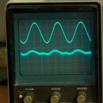
The SP-6 Light can easily output 20V RMS without clipping.
Without the HF compensation, the distortion at mid frequencies 2.965 Hz did not change. So I stopped with the compensation al together. I found this improves the sound!
HF roll-off
The input circuit has a very high impedance: the 1 M grid load is amplified some ten times because of the way the feedback works. This means the interface to the potmeter worked fine. It is a 50k grey Alps. Turning the volume down does not change the HF roll-off significantly:
0 dB 202 kHz
-3 dB 133 kHz
-6 dB 112 kHz
-12 dB 113 kHz
-18 dB 143 kHz
That is a good designed input stage! A test with a 20pF grid/cathode cap like in the original circuit did not significantly increase the HF roll-off point further.
Sound
Linked to my F5 and Quad 57.
Extreme dynamics. No projection. Sound envelops the speakers (Quad 57 standard feet).
Solid bass. Bass and mid bass are handled extremely well.
The sound is slightly in front of and on the sides of the speakers. But there is no hard projection of sounds. No ‘solid state’ vertical wall. That is very good.
Different layers in the music like a-capella singing are well conveyed. I even heard a singer having a slight dubbed double. Reflection? Small sounds in the background like vocalists can be heard, little loops on the instruments.
It is quite an improvement over the 6SN7 Aikido.
SP-6 Light Specs:
bandwidth from <2 Hz to >150 KHz, flat (less than 0,5 dB).
20V RMS output possible, fast rise time.
12,5 dB amplification.
Distortion: less than 0,01 %
Noise level: not measurable. And not audible, no hum.
Bandwidth stays rather constant with a potmeter of 50k: a very good sign. This implies the sonic signature stays constant (unlike other topologies!).
Square wave 53 kHz with 18 pF feedback (top trace):

Distortion
Distortion measurements, prototype with/without HF roll-off in feedback and on anode/grid:
Generator 2.965 Hz
+ 20 dB 7 V RMS < 0,02%
+ 10 dB 0,7 V RMS 0,008%
with positive feedback applied, 330k between cathodes: 0,02% (increased)
With 18 pF on 33k feedback: less noise visible on screen and the distortion dropped. It was visible on the scope (the difference signal from the distortion meter).
Visibly, but unmeasurable, there is a hint of 2nd harmonics.
I conclude that it is not needed to use the positive feedback. So I dropped it.
Distortion at 2 volt RMS out, <0,01%

The SP-6 Light can easily output 20V RMS without clipping.
Without the HF compensation, the distortion at mid frequencies 2.965 Hz did not change. So I stopped with the compensation al together. I found this improves the sound!
HF roll-off
The input circuit has a very high impedance: the 1 M grid load is amplified some ten times because of the way the feedback works. This means the interface to the potmeter worked fine. It is a 50k grey Alps. Turning the volume down does not change the HF roll-off significantly:
0 dB 202 kHz
-3 dB 133 kHz
-6 dB 112 kHz
-12 dB 113 kHz
-18 dB 143 kHz
That is a good designed input stage! A test with a 20pF grid/cathode cap like in the original circuit did not significantly increase the HF roll-off point further.
Sound
Linked to my F5 and Quad 57.
Extreme dynamics. No projection. Sound envelops the speakers (Quad 57 standard feet).
Solid bass. Bass and mid bass are handled extremely well.
The sound is slightly in front of and on the sides of the speakers. But there is no hard projection of sounds. No ‘solid state’ vertical wall. That is very good.
Different layers in the music like a-capella singing are well conveyed. I even heard a singer having a slight dubbed double. Reflection? Small sounds in the background like vocalists can be heard, little loops on the instruments.
It is quite an improvement over the 6SN7 Aikido.
- The preamp asks, no begs, to be set louder! Now that is a compliment.
SP-6 Light build
Some pictures
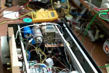
A top view of the SP-6 circuit in my existing cabinet.
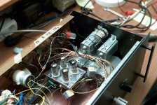
The bottom of the amplifier. Now this is point to point soldering! (apologies for the mess. This is what it looks like while experimenting . . .)
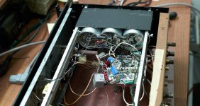
To the side there are three 40 muF MKP capacitors that form the final stage of the power supply.
The output caps
The ALPS volume pot
Some pictures
A top view of the SP-6 circuit in my existing cabinet.

The bottom of the amplifier. Now this is point to point soldering! (apologies for the mess. This is what it looks like while experimenting . . .)

To the side there are three 40 muF MKP capacitors that form the final stage of the power supply.
The output caps

The ALPS volume pot

Last edited:
The power supply for the SP-6 Light
Power supply SP-6 Light
I reused the components of my Aikido (everything was there already) but I changed the configuration dramatically: from a traditional CLCLC (10mu/25H/1.200mu/3H/10mu) to a choke loaded circuit LCLC: with a choke up front.
Advantage: you get reduced ripple, low load on the trannie (you can't get saturation this way) and load regulation all at once.
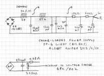
I took the 3 H (70 ohms DC) choke directly after the rectifier, then 10 mu, subsequently the hefty LC pair of 25H/1.500 mu. While in the old configuration I had a lot of mains residue, now none was left!
On my B&K: 2 volts RMS in cell 1, 2 mV cell 2 (with 3-5 mV line fluctuations).
And this configuration provides regulation, with 225AC in I get around 245 plus or minus 5 volts out for a range of current.
Heaters are DC. The 0,68 ohm drops the 7V to 6,15 V. With the PCC88 I will connect directly to the +7V, and increase the series resistor to 1,2 ohm or I will insert a transistor.
Not shown, a muting temporization circuit (using IRF640 driving a relay and a slow start delay of a resistor and capacitor that shunts the output with 2k for 10 seconds) is fed from a 12V winding.
I now use a 225 AC winding; my transformer has a 250V and 275 V winding too so I plan to add a tube rectifier and use this as an additional slow start option.
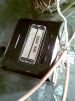
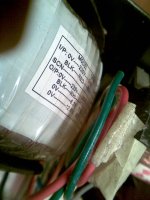
The transformer (Yes it is BIG)
The power supply. The 3H choke for the choke loading is on the right top.
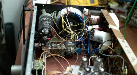
The bottom of the power supply. You can see the array of the 1N3883 power diodes and the 25H second choke as well as the Felsic 1.500 400V electrolytic.
Power supply SP-6 Light
I reused the components of my Aikido (everything was there already) but I changed the configuration dramatically: from a traditional CLCLC (10mu/25H/1.200mu/3H/10mu) to a choke loaded circuit LCLC: with a choke up front.
Advantage: you get reduced ripple, low load on the trannie (you can't get saturation this way) and load regulation all at once.

I took the 3 H (70 ohms DC) choke directly after the rectifier, then 10 mu, subsequently the hefty LC pair of 25H/1.500 mu. While in the old configuration I had a lot of mains residue, now none was left!
On my B&K: 2 volts RMS in cell 1, 2 mV cell 2 (with 3-5 mV line fluctuations).
And this configuration provides regulation, with 225AC in I get around 245 plus or minus 5 volts out for a range of current.
Heaters are DC. The 0,68 ohm drops the 7V to 6,15 V. With the PCC88 I will connect directly to the +7V, and increase the series resistor to 1,2 ohm or I will insert a transistor.
Not shown, a muting temporization circuit (using IRF640 driving a relay and a slow start delay of a resistor and capacitor that shunts the output with 2k for 10 seconds) is fed from a 12V winding.
I now use a 225 AC winding; my transformer has a 250V and 275 V winding too so I plan to add a tube rectifier and use this as an additional slow start option.
The transformer (Yes it is BIG)

The power supply. The 3H choke for the choke loading is on the right top.

The bottom of the power supply. You can see the array of the 1N3883 power diodes and the 25H second choke as well as the Felsic 1.500 400V electrolytic.

Initial SP-6 Light build findings
Overshoot
My initial prototype had enormous overshoot as well as motor boating. I could not get that out of the system, I once even got HF oscillations, but that helped me find out why: with little steps of improving the layout I got the configuration to work. Besides layout it was the output buffer in one channel.
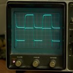
The first prototype stuffing was with 10nF/1M intermediate stage, no input stopper, and had a lot of overshoot in both channels, but most in one channel: on the downward slope, so I almost discarded the whole idea.
Severe 'down-shoot' on one channel, bottom trace
I added the trim cap (5-45pf) and could influence the rising edges of the square wave a lot, but it stayed awkward.
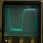
After days of experimenting I found out a first reason for the bad behavior: I had no stopper resistor so the signal generator bounced against my input. The circuit has 1k8. I tried 20k and 2k and finally settled for 12k as a nice value that gave me ample space for trimming the square wave.
The result was now as follows: one channel with 18pF and the other the input trimmer optimised:
Motor-boating
Another big problem was that initially the circuit motor-boated (low frequency fluctuations). I found out that the coupling cap is important. Taken too small (I started with 10 nF/1M) you get a lot of motor-boating. With the low overall amplification I needed to increase the size. Low frequencies square waves had a hard time of getting through the two stages with the initial small coupling cap, I saw. I also noted that a small size makes the amplifier sensitive to the power supply – it passed fluctuations almost 1:1. With 100nF/1M this motor boating disappeared. The original SP-6 circuit value has the same point: 220nF/470k. I used a mu stage anode load, this also increased the risk of motor-boating.
What is motor boating: Having too small a size gives slow variations in the range of 2-20 seconds shifts (I mean sub Herz fluctuation) of several 100 mV to a volt on the output before the cap; this shift in the DC levels influences all working points. It comes from the one coupling cap introducing a pole in the feedback. A DC based coupling between the stages will solve the problem. I tried it but did not finish the experiments because I saw some HF roll off.
With a DC amplifier like the F5 and a big cap of 2 muF you WILL notice.
I tested the prototype and started off with an ECC83 combined with ECC85 for the output buffer. The advantage over an ECC88: it can easily be converted to a mu-stage - for instance with a 4k9 in the cathode lead and I tried the ECC85 also with a 2SK30 0,5 mA current source as cathode load. The reason for the mu-stage: then there is never any problem of arcing of the output buffer at warming-up.
Tubes
With the ECC83 the feedback is enormous. The open loop was almost 75 dB, then down to 12.5 dB is quite a lot of feedback. The original circuits has 50 dB feedback. I looked at lower mu tubes and I decided to go for the ECC81, reputed for its good sound. It is used as the tube in my Revox line stage (a Studer built unit). I have several ECC801S, long life types.
The ECC82 works too.
Solving overshoot?
There is an input cap C1. I first had this cap directly on the tube pins and in this way placed in a crowded environment between the other components – in that way I found out it gives stray capacitances. I then placed the stopper resistor of 12k on the pins getting the input cap outside of the component board. This was my most important change!! It solved most ringing problems. But it stayed in one channel. The change meant that the input cap did not have a proximity effect anymore (pick up stray airborne Heaviside radiation. Heaviside said around 1910 that there ius more energy outside of the conductor than inside . . .).
I can imagine a PCB implementation that is completely perfect in the placing of components.
The coupling cap C2 between first/second stage did seem to matter too because the various types I tried had quite different amounts of ringing (but the problems I had could afterwards be due to proximity coupling with the input cap, see above). For instance I had the counterintuitive result that a 10nF mica hade more ringing than a MKC – but that was standing out from the socket with 4 cm. Stray radiation again?. I added a 1k2 stopper resistor here, but that had no visible effect. Anyway, at the end I again settled for a 100nF/1M coupling.
I used a 18pF cap on the feedback resistor. This reduces the bandwidth to something like 270 kHz and gives a smooth square wave. Without it I can trim the square wave with C4 and get a minuscule ringing (overshoot) around 400kHz. (See picture above).
The components in the feedback also seemed to matter (but again - I had initial layout problems and a buffer issue). I tried 37k wire wound NI but this looked worse. So I settled for carbons.
But looking back the bad effect I thought it might probably due to a worse alignment of parts.
- - - But I will revisit this ringing again . . .
(at the end I found out the ringing in the left channel came because of a bad buffer tube – not bad layout or components!!!)
Overshoot
My initial prototype had enormous overshoot as well as motor boating. I could not get that out of the system, I once even got HF oscillations, but that helped me find out why: with little steps of improving the layout I got the configuration to work. Besides layout it was the output buffer in one channel.
The first prototype stuffing was with 10nF/1M intermediate stage, no input stopper, and had a lot of overshoot in both channels, but most in one channel: on the downward slope, so I almost discarded the whole idea.
Severe 'down-shoot' on one channel, bottom trace

I added the trim cap (5-45pf) and could influence the rising edges of the square wave a lot, but it stayed awkward.
After days of experimenting I found out a first reason for the bad behavior: I had no stopper resistor so the signal generator bounced against my input. The circuit has 1k8. I tried 20k and 2k and finally settled for 12k as a nice value that gave me ample space for trimming the square wave.
The result was now as follows: one channel with 18pF and the other the input trimmer optimised:

Motor-boating
Another big problem was that initially the circuit motor-boated (low frequency fluctuations). I found out that the coupling cap is important. Taken too small (I started with 10 nF/1M) you get a lot of motor-boating. With the low overall amplification I needed to increase the size. Low frequencies square waves had a hard time of getting through the two stages with the initial small coupling cap, I saw. I also noted that a small size makes the amplifier sensitive to the power supply – it passed fluctuations almost 1:1. With 100nF/1M this motor boating disappeared. The original SP-6 circuit value has the same point: 220nF/470k. I used a mu stage anode load, this also increased the risk of motor-boating.
What is motor boating: Having too small a size gives slow variations in the range of 2-20 seconds shifts (I mean sub Herz fluctuation) of several 100 mV to a volt on the output before the cap; this shift in the DC levels influences all working points. It comes from the one coupling cap introducing a pole in the feedback. A DC based coupling between the stages will solve the problem. I tried it but did not finish the experiments because I saw some HF roll off.
With a DC amplifier like the F5 and a big cap of 2 muF you WILL notice.
I tested the prototype and started off with an ECC83 combined with ECC85 for the output buffer. The advantage over an ECC88: it can easily be converted to a mu-stage - for instance with a 4k9 in the cathode lead and I tried the ECC85 also with a 2SK30 0,5 mA current source as cathode load. The reason for the mu-stage: then there is never any problem of arcing of the output buffer at warming-up.
Tubes
With the ECC83 the feedback is enormous. The open loop was almost 75 dB, then down to 12.5 dB is quite a lot of feedback. The original circuits has 50 dB feedback. I looked at lower mu tubes and I decided to go for the ECC81, reputed for its good sound. It is used as the tube in my Revox line stage (a Studer built unit). I have several ECC801S, long life types.
The ECC82 works too.
Solving overshoot?
There is an input cap C1. I first had this cap directly on the tube pins and in this way placed in a crowded environment between the other components – in that way I found out it gives stray capacitances. I then placed the stopper resistor of 12k on the pins getting the input cap outside of the component board. This was my most important change!! It solved most ringing problems. But it stayed in one channel. The change meant that the input cap did not have a proximity effect anymore (pick up stray airborne Heaviside radiation. Heaviside said around 1910 that there ius more energy outside of the conductor than inside . . .).
I can imagine a PCB implementation that is completely perfect in the placing of components.
The coupling cap C2 between first/second stage did seem to matter too because the various types I tried had quite different amounts of ringing (but the problems I had could afterwards be due to proximity coupling with the input cap, see above). For instance I had the counterintuitive result that a 10nF mica hade more ringing than a MKC – but that was standing out from the socket with 4 cm. Stray radiation again?. I added a 1k2 stopper resistor here, but that had no visible effect. Anyway, at the end I again settled for a 100nF/1M coupling.
I used a 18pF cap on the feedback resistor. This reduces the bandwidth to something like 270 kHz and gives a smooth square wave. Without it I can trim the square wave with C4 and get a minuscule ringing (overshoot) around 400kHz. (See picture above).
The components in the feedback also seemed to matter (but again - I had initial layout problems and a buffer issue). I tried 37k wire wound NI but this looked worse. So I settled for carbons.
But looking back the bad effect I thought it might probably due to a worse alignment of parts.
- - - But I will revisit this ringing again . . .
(at the end I found out the ringing in the left channel came because of a bad buffer tube – not bad layout or components!!!)
Tips
Connect the stopper resistor at the input to the pins directly to overcome the tendency for oscillation.
At start-up the grid of the output ECC88 is at Vb while the cathode is at ground: it will arc. A diode must be inserted here to prevent the arcing. This would otherwise reduce the life of the output tube to tens of hours . . .
Use a good muting temporization in the start up. Otherwise you will have big plops. I have 10 sec temporization, at 2k. Once it releases the output of my AF5 (+15 dB) does not rise above 2,5 V DC. It might be a good idea to insert a grid leakage choke here, 150H, 600 ohms resistance.
I do find that there is a difference in warm-up of the ECC801S and the PCC88. The PCC88 comes up later. Have to look into that.
In my old 6J6/E90CC line stage that I had for more than 10 years, I had an attenuator inside the loop of -15dB: that worked fine and gave a very natural sound. (I needed it for a DC balancing of stages). I can do the same here in this SP-6. The open loop gain will be reduced getting a better sound stage back.
Of course it will work too with an ECC82. The anode and cathode resistors values allow inserting in ECC82 too, this will reduce the gain. The open loop amplification is then around 40 dB. This was my first prototype back several years ago. I can now easily roll tubes of course . . .
In my Aikido I needed to renew tubes every two years: too high a cost for me. A DHT like the 10Y or 300B can run for 15.000 hours with ease. Now that implies economy. The high cost pays for itself.
The input tubes I have chosen are Radiotron ECC801S. These mil-spec tubes have a long life of >10.000 hors too as long as the turn on/off cycles are well managed (2.000 cycles at 7,5V DC applied at start up) and the heater/cathode voltage is not high. The tube can be kept on (heater on) without DC indefinitely. So a good option would be to just switch the HV. I have my heater at 50 volts, near the input cathode value.
An update
.
Do I miss anything? Just from my last experience, where the Yamaha soundstage impressed me. Wonder why. Maybe I should revisit the Hiraga implementation of the Kanéda line stage, the topology Yamaha also uses?
And the highs still at a few moments have a small coarseness.
And a few times the mid frequencies tend at time to come from a too small spot in the middle of the speaker. A convoluted image. A very small vortex. Must have to do with all the feedback.
21/4 So after a lot of tampering, one channel is very good, square wave without overshoot, no trimming caps and no feedback caps. The other channel however still has a 5% ringing in the 3 Mhz area. The down-shoot. See picture above, bottom trace. I can’t get that out!
Tried other interstage coupling caps, other stopper resistors. No improvement. Tried reducing amplification in second stage – no effect. It must be a layout problem?
Rolled tubes and that way found out: the overshoot comes from a bad ECC88 in the output. One had a problem. This made the large overshoot. Replacing the tubes with PCC88 (I don't have more ECC88’s) I have the same very small overshoot in both channels now. Maybe I should try another output tube.
Tried ECC82. Did not look better on the scope. Does work though.
Have now Westcap fitted input cap 0,47 muF. Might be bit bright.
As a special experiment I did the following. Tried a DC based attenuator between the stages 1 and 2: in fact an interesting concept, to attenuate 20 dB here and achieve a level shift, while increasing the cathode resistor. The concept: a divider from the anode of the first stage of 330k/26k with 5 k extra Rk2 so this brings about 10 volts on the grid, 2 mA in second stage like it was. In fact the 10 volts off was lower: the load over the Ra of the first stage increased dropping the Va. This has bad effects on things like bandwidth. The rise time was significantly low, meaning there is a high roll-off that I did not measure - just by observation. Is an interesting thing to study though, and must be balanced with a lower Ra for the first stage and a higher Ra for the second stage (to come to 125V for the buffer again). Something for a simulation. Potentially very strong! (I had such a DC adapter in another preamp many years ago.)
So I settled for the version without feedback cap and without a trimmer at the input (compensation caps already shown as optional). NowI see a 3MHz rise in output level (shelving to 5MHz). On a 50KHz square wave you can see it (small overshoot specifically going down) but in practice – I don’t feed the raw NOS output from the DAC to the speakers. . .
It is often like this: measurements (such as a slightly visible overshoot) do not say a single thing about natural sound.
Again in the listening room.
Now without any BW-limiting artifices like input trimming capacitors and feedback capacitors. Just a 820 ohm stopper resistor. Incredible transparency. At every position of the volume pot! This is what I aimed for! Hyper dynamic yet no vertical sound wall.
My TDA1541 S1 DAC really shines when I listen at full volume, and man, this is great.
I listened to some nice edited CD’s. I like BIS recordings for their very dynamic recording style. So what about the Montagues and the Capulets (Prokofiev Romeo & Juliet) track with Christian Lindberg himself? Incredible directness on the left channel with Christian just standing in my room. Then I tried a track of the percussionists in Stonewave from Wallin, a good potpourri of a difficult to track session but now it is an utterly enveloping sound stage.
Man does this line stage want me to sit during the whole night!
The sound stays the same independent of the volume setting. The same dynamics, the same punch. Something I was looking for after I had heard Guido Tent’s system.
So I also ran to my record collection, and there I was even more happily surprised. Just for the late night I played Alfred Deller a counter tenor as well as Nico + The Faction, and listened to her nice German accent, both slightly high in pitch though - this showed up that my RIAA is a little bright, I’ll remedy that quickly (I have made an anti-RIAA already to test). Funny, my 6SN7 Aikido never showed that slight brightness above around 2 kHz. In fact that combo was sorta all right. The RIAA is without any feedback, and little ticks did not annoy at all.
This means this line stage is very very well behaved, also in the super-sonics. There was no need for me to be so scared of the 2M6-3M small bump in the bandwidth.
Meten is niet weten.
next steps:
I mentioned a slight brightness in records: It could be the Westcap (bottom) is the source of brightness? Should I try the Styroflex (top) again? First I will check my RIAA with an anti-RIAA circuit.
Attachments
2SN7 version
Today I rechecked the implementation.
I implemented a 6SN7 version: same phenomenon as above though less exaggerated unless pushed very hard.
I saw that the second stage overloads the output, when this downward sag exists. This is even better visible with the 6SN7.
As I stripped down the circuit I found out that the circuit sans the cathode follower was OK: flat to 320 kHz. At 10 V RMS out. Perfect square rise times, maybe not wholly symetric, but very good.
Then I reinserted the CF, and added a parallel load resistor of 18 K. This solved the whole problem. The issue came from starvation of the CF!.
Now there is no overshoot, the circuit with 6SN7 is flat from <2 Hz to 380 kHz.
And very dynamic I expect.
albert
6SN7 version, pictures
To start off, I have a picture of the problem area of the first config. This shows the output (53 kHz, 10 V RMS) at the anode of the second stage and the output of the CF: it is clear the CF is starved, the driver overloads it.
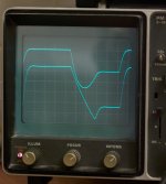
So I just added a resistor to earth, with a dummy load of 5 mA, and this solved the whole problem:
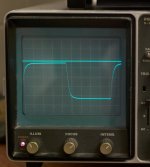
Here you might suspect the falling edge to remain a little bit constrained (straight line). I checked that with a 100 kHz square wave of 10 V RMS out, to review the alignment.
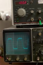
A sine shows the lines are perfectly aligned now, there is only a bit of phase lag and the odd dB of insertion loss (that is normal for a CF). The HF roll off is above 380 kHz. It is very smooth, no artifacts.
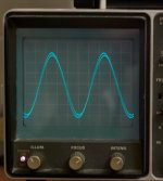
This definitely is promising isn't it?
To start off, I have a picture of the problem area of the first config. This shows the output (53 kHz, 10 V RMS) at the anode of the second stage and the output of the CF: it is clear the CF is starved, the driver overloads it.

So I just added a resistor to earth, with a dummy load of 5 mA, and this solved the whole problem:

Here you might suspect the falling edge to remain a little bit constrained (straight line). I checked that with a 100 kHz square wave of 10 V RMS out, to review the alignment.

A sine shows the lines are perfectly aligned now, there is only a bit of phase lag and the odd dB of insertion loss (that is normal for a CF). The HF roll off is above 380 kHz. It is very smooth, no artifacts.

This definitely is promising isn't it?
Pushing the limits of the E801S version
After this succesfull experiment with the 6SN7 I reverted to the version in the living room to adapt what I just learned with the 6SN7 experiment: get a higher current for the CF. 3 mA plus looked rather good to me as it was, but I added a dummy resistor also here to earth, that consumes 2,5 mA.
This gave more air definitely. The - 3 dB bandwidth is now an astonishing 687 kHz. This limit is clearly slew-rate limited (downward slope), so the buffer can be optimised further. The bandwidth could then reach 1 MHz easily ... No overshoot on the square wave, a slight nervousness can be seen on the settling edge (not an oscillation). With the 6SN6 you can see a relaxed settling, here with the 801S it bam locked. It is the higher feedback.
The 801S listening is ultra dynamic. It highlights all nuances of the music, small changes of timbre in the highs and lows, in pitches and in placement. The low level details are astonishing: even in the bass frequencies.
I did adapt the resistances a bit to improve the operating points. The first anode load went up to 150 K, the second was reduced to 39 K.
Distortion measurements, 6SN7 version
This is the picture of the distortion, at 10V RMS out:
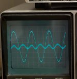
Almost pure 2nd harmonics. My meter says 0,1%. But that figure itself is distorted: the distortion shows the bad regulation of my bench top power supply as the thickness of the trace.
The square wave of 100 kHz: pure music.
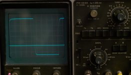
This is nice behavior, no RC in the feedback, no HF shunt in the first stage . . .
Because of the circuit adaptions, I should not call it an SP-6 clone anymore.
This is the picture of the distortion, at 10V RMS out:

Almost pure 2nd harmonics. My meter says 0,1%. But that figure itself is distorted: the distortion shows the bad regulation of my bench top power supply as the thickness of the trace.
The square wave of 100 kHz: pure music.

This is nice behavior, no RC in the feedback, no HF shunt in the first stage . . .
Because of the circuit adaptions, I should not call it an SP-6 clone anymore.
I have implemented a shunt DC for the heater of the 6SL7 tubes. It has a slow start with an idle current of 120 mA for about 5 seconds, before the voltage is slowly increased. This way, there is no surprise for the tubes.
View attachment Power Supply RIAA V3.pdf
The result is excellent. After about 15 minutes of warming up, the amplifier is full and warm blooded.
I have the 6SL6 in series because the winding I have is 12.3 V nominal (actually more than 13), so I could have cut the winding into two parts (the winding of the center tap is available), but that would double my components...
The schema works at this lower voltage too, but resistances have to be adjusted for 6.25 out.
The drop over the slow start FET is < 0,1 V. So it is negligible. This FET does not have a heatsink.
Very Interesting Albert, where are you now in this preamp ? May we get the definitive circuit and pictures ?
I am very in to this amplifier!
- not physically: I finished it quite some time ago and have not found reason to adapt anything. It is just marvelous.
I might though implement a small kind of bandwidth correction of + 2 db from 200 Hz down just because I have these Quad ELS that are a bit lean in the bass and on some sources this is noticeable at low sound levels; it is a light kind of physio you might call it.. But is is also the difference between the 300B amp (higher output gives a little boost in the low end) - and my F5 that can pump 15 amps
I see I left some things to the imagination:
http://www.diyaudio.com/forums/atta...1335184329-sp-6-light-ecc801s-sp6-final-2.jpg
But I omitted C4 and C5 altogether. Also I did not use the positive feedback of R14. At the end on the distortion analysis I think I did not like it; but audibly I heard no high extra dynamics. So conclusively I decided for keep it simple.
The value of R14 also has impact on the setting of the whole amplifier and would have required too much experiments to get a good value where its effect is audibly positive. I think with all the feedback its impact is also negligible and thus might result in higher order distortion, invisible for me.
I must say I have an old fashioned distortion meter and can not see more than about third harmonics.
I might have a look again at the final resistor values (R10, R11) what I finally did use.
hope this helps you
albert
Thanks Albert, it's much infomative. I of course did not intend to put you in the box, sorry for my approximative command of English  -(
-(
I understand that there should not be too much tuning after power on ? I can copy slavishly but not go into too skilled practice unfortunately.If so, I may give it a try in a couple of months when finished optimizing my Dac.
Did you have opportunities to compare the SP6 clone to other preamp ?
BR
I understand that there should not be too much tuning after power on ? I can copy slavishly but not go into too skilled practice unfortunately.If so, I may give it a try in a couple of months when finished optimizing my Dac.
Did you have opportunities to compare the SP6 clone to other preamp ?
BR
Oops I forgot something.I understand that there should not be too much tuning after power on ? I can copy slavishly but not go into too skilled practice unfortunately.If so, I may give it a try in a couple of months when finished optimizing my Dac.
Did you have opportunities to compare the SP6 clone to other preamp ?
BR
The point I found out experimentally is just that there needs to be enough current in the cathode follower, that was the biggest find. That is why there are two resistors to ground from the cathode: one to the input divider and one directly to ground.
I have described it in a later post:
It has a nice slow start, just a few seconds and the sound starts. Even power off is without a pop. And that with a hefty triode stage pre into a very heavy solid stage power amp.I added a dummy resistor also here to earth, that consumes 2,5 mA. At Vk 100-120V this is 39-43K.
The first anode load went up to 150 K, the second was reduced to 39 K.
I compared it with the Aikido 6SN7 and it is just a bit more dynamic, in the sense that the sound stage at any level is constant and has a very big depth. This characteristic is what I like most in an (pre)amp, some call it laid back. The Aikido is not bad though. Just a little less coloring, and it can't handle long capacitative interlinks as good as this preamp (>500pF).
I also had a nice balanced preamp, but I had that with 7 pin dual triodes, that shared the cathode, and these were microphonic, even so that when I turned the stepped pot I heard ringing and with heavy crescendo's this also happened. In my memory that was a very nice design too (I had it for 15-20 years).
Since I finished it, I never touched it again.
The new Current Feedback preamp with ECC88.
I found I had some rectifier sound in the output. When I connected a Lowther to my power amps (PP 300B) there was a big 'buzz'. And there was a also some hiss. Without the preamp the power amp was completely silent. Even with the 5V filament in AC...
So I went ahead in fixing the preamp, and in the mean while - - - I redesign the whole lot.
I tested the input with a LED as current source at the cathode. But this was very noisy (the LED's zener noise is amplified...); even connecting a cap across it did not help. So I selected a resistor to give the same 1,88 V drop (1,8-2 k).
So I have simplified version here that I like much again.
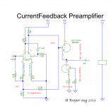
I found I had some rectifier sound in the output. When I connected a Lowther to my power amps (PP 300B) there was a big 'buzz'. And there was a also some hiss. Without the preamp the power amp was completely silent. Even with the 5V filament in AC...
So I went ahead in fixing the preamp, and in the mean while - - - I redesign the whole lot.
- A first design decision was, that if I wanted to get a preamp with the lowest noise floor, I should revert to E88CC or even E188CC in the first stage.
- I would need a very silent HV, so I installed a Salas HV at 200V.
- Noisy ECC88?? Well a subsequent find was that the heater influenced the cathodes. I had the heater at plus 50 volts (I thought) but measuring, it was lower (20V), so something was wrong. I connected a mA meter and found some 3 mA were dumping in the cathodes. The heaters were at a divider of 68K/20K. It just disappeared when I connected the heater center to earth. Then also the noise in the tubes disappeared (for a large part). I found the tubes to be most silent when I connected it with 20K, bypassed to earth; the current was then 0,0145 mA.
- I took all care to get a star ground. Both halves and the output stage are connected separately to the ground and plus.
- I also decided to omit the feedback from the cathode follower and revert to a proper line stage feedback, directly from the first anode to the input cathode. I had seen before this gives no overshoot, is perfectly stable and is wide band: from < 1 Hz - > 350 KHz. So all problems I had of loading the output before, from slew rate limiting are gone all at once.
I tested the input with a LED as current source at the cathode. But this was very noisy (the LED's zener noise is amplified...); even connecting a cap across it did not help. So I selected a resistor to give the same 1,88 V drop (1,8-2 k).
So I have simplified version here that I like much again.
Note I have reverted to ECC88's and I must mention the two halves are not similar! The first triode half (1,2,3) has a Vfk of 150V, the second one (6,7,8) of 50V. So I must use the first one in the entrance because it floats at +55V ; the second one is used for the second stage. In the CF output I have (1,2,3) on top of the cascode-connected CF, and the section (6,7,8) as the constant current source. Because of the CCS I do not need a diode safeguard between the top grid (2) and the cathode/anode (3;6). I always suspect these diodes of some sonic effect.

Attachments
- Status
- This old topic is closed. If you want to reopen this topic, contact a moderator using the "Report Post" button.
- Home
- Source & Line
- Analog Line Level
- SP-6 Light with ECC801S
