Howdy
I'm repairing a mixing board channel that has a malfunction in the line input stage.
My best guess is that the line level transformer has gone kaput.
How can i check if the transformer is working properly?
I have a multimeter and a oscilloscope, no audio voltmeter.
Should I test the board with current flowing trough or can i test it without current?

I'm not sure if this is the right forum to ask this.
Do you guys know of other forums on electricity where i can search for circuit repairing tips?
I'm repairing a mixing board channel that has a malfunction in the line input stage.
My best guess is that the line level transformer has gone kaput.
How can i check if the transformer is working properly?
I have a multimeter and a oscilloscope, no audio voltmeter.
Should I test the board with current flowing trough or can i test it without current?
I'm not sure if this is the right forum to ask this.
Do you guys know of other forums on electricity where i can search for circuit repairing tips?
Hi. First, check continuity and or interwinding shortcircuits. Second, apply some low voltage at one winding, and verify if some other voltage appears at the other(s) winding, don´t care the voltages appearing, it important that some voltage are in them. If it is the case, the trafo is OK, except that it has hum pickup or some frequency resonances and or leakages.
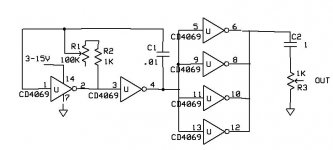
An easy way to inset voltage, is to make a 555 or a HCF4069 oscillator, say, 1KHz squeare wave (near 50% duty cycle) and capacitively couple to any winding (to don´t saturate the core with the DC mean current) , and verify if this signals comes out from other wires.
Good luck..
An easy way to inset voltage, is to make a 555 or a HCF4069 oscillator, say, 1KHz squeare wave (near 50% duty cycle) and capacitively couple to any winding (to don´t saturate the core with the DC mean current) , and verify if this signals comes out from other wires.
Good luck..
NEVER TEST AN AUDIO TRANSFORMER WITH DC! It will damage it and increase the distortion. Plug in a dynamic microphone and look at the secondary with the oscilloscope. Tapping on the microphone should give you a signal of tens of microvolts to several millivolts. You can also use an Ipod or CD as a source for the test. Just be sure to use input pins 2 & 3 the ground is often not required.
Hi Osvaldo
Thanks for the reply
Should i take the transformers out of the circuit for that?
If the problem is in another part of the circuit, will it affect the test?
I'm comparing the a malfunctioning board channel to one that is working.
I'm sending a square wave from a signal generator to the primary of the transformer and reading in the secondary.
The secondary appears to have a roll off in the high harmonics, in the good channel and in the bad channel, but it passes voltage.
When I send a signal to the line input of the channel, I can hear it in the output, but with less level and it sound's all mid rangy
Hi Osvaldo
Thanks for the reply
Should i take the transformers out of the circuit for that?
If the problem is in another part of the circuit, will it affect the test?
Yes, but add some kind of manual attenuator at the output of the oscillator, a 1k pot will work properly. Also, if you make the HCF4069 oscillator (using 2 units of 6 inverters inside it for oscillator itself, and the other 4 wired in parallel as "output stage"), it will work with as little as 3V, so I believe that such a voltage will not damage any kind of circuit.
Sorry by the ugly look, but I did it while eating, ouch!!!
Don´t use a too low R2 or the oscillator will stop.
Attachments
Further data: if you have a oscilloscope, you can measure the turns ratio comparing input and output amplitudes, a bit more difficult with true audio. Also, ringing at the vertical edges and or rounding corners, gives you an idea of how well is the trafo under question.
As Simon tells, don´t use DC to measure audio xformers, they may become magnetized and then increase distortion. Such low level units has very high mu cores, and can get strong remanence with low currents in its windings. For that reason I underlined capacitively couple the trafo to the test gear (Oscillator). It prevents DC flow in the coil.
If you had done the test, and the outs of the xformers looks too different, may be a trouble outside it, may be a diode to +B and one to -B (or gnd) to prevent destroying the amplifier from leakage discharge, and or a zener to cut them), and may become faulty.
Luck!!!
Last edited:
The transformer is good. The next test is to send the signal into the good channel and look at the output of the opamps. Just touch the scope probe to pins 1, 7, 8, & 14 on the larger chips and pins 1 & 7 on the smaller packages. Compare what you get to the bad channel. Once you find the difference look for smoked or leaking parts.
Can I test capacitors without desoldering them from the board?
Definitively NO!! Capacitors in the power buses has lot of things in parallel: resistors, voltage dividers, diodes, transistors, etc, so not only a cap measure, and a leakage will be horribly erroneous. The only case is if the cap has leaks in the down part of them, between pins and rubber seal. Nichicon caps and some chinese cheap capacitors becomes leaky and the PCB result damaged by internal cap juice. And as it is conductive, it can affect circuit traces, corroding them chemically and adding shunt resistance in the circuit.
I just have one question that will really help me in solving this problem.
Can I test capacitors without desoldering them from the board?
Well, definitely maybe. That's why people like high frequency ESR testers as you can easily detect a cap that has a lot of loss in circuit. I test caps in circuit all the time with little trouble using a standard cap meter with a loss function. The surrounding circuitry will almost never make a bad cap look good. So, if you find a cap with the wrong value or a lot of loss, that's when you should lift a lead or pull it entirely out of the circuit to test. As said above, it's usually the caps in the power bus that will give uncertain readings. If you have a schematic it should also be obvious if the cap has a lot of resistive circuitry in parallel. More cap info on my site.
Well, definitely maybe.
Some extraneous. I don´t agree. Let´s suppose a single stage transistor to transistor rc coupled. Assume a 10K collector load, and two 100K base bias. Also assume a 10uF electrolytic coupling cap. The cap sees a 110K in parallel with it assuming no DC resistance between buses. The cap is OK, but the 110K will be read as DC loss. Mmmm, don´t like such a test!!!
Naturally it depends on what you have to test with, which is why I push bridges and meters having a loss function (dissipation factor, esr or whatever units you prefer). Taking that 10 uF cap with 110 kohms in parallel, that's a dissipation factor of about .00015 (1 kHz), which is many orders of magnitude under what any electrolytic can manage. That's Teflon, polypropylene or polystyrene territory. Or, taking it as Rs (ESR), that's about 2.4 milliohms. Thus, the surrounding circuitry will have no effect on ones determination if the cap is good or bad. Now, DC leakage is definitely something you have to measure out of circuit if you think its a problem. I don't see significant DC leakage very often, and the cap will usually have some other obvious problem as well, but for one case. I've seen caps on the grid of a tube where the tiniest amount of leakage will mis-bias the tube, with disastrous results. Fortunately nobody with any sense uses electrolytics there. So, with a decent bridge or capacitance meter, in-circuit measurements are very practical in most cases. One just has to use some judgement about when the results are questionable, or the nature of the fault, and in those cases pull the part to be absolutely sure.
Last edited:
- Status
- This old topic is closed. If you want to reopen this topic, contact a moderator using the "Report Post" button.
- Home
- Source & Line
- Analog Line Level
- Transformer malfunction??'