How did Au get it so wrong?
Who is the designer?
AU? you mean me ?
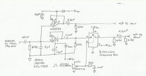
Who's the designer. Well you could blame many people because I patched the whole thing together using various sources for my design; Forrest Mims, datasheets from the Internet and my own (limited) electronics knowledge.
Aucosticraft asked for the latest revision of the schematic to I've attached that to this post for your information.
Thanks again everyone for your help in this project. It has been a pleasure working with you and a great satisfaction to have discovered a solution. I am very grateful.
Vielle568
Aucosticraft asked for the latest revision of the schematic to I've attached that to this post for your information.
Thanks again everyone for your help in this project. It has been a pleasure working with you and a great satisfaction to have discovered a solution. I am very grateful.
Vielle568
Attachments
Another thought on the opamps and so on.
The 5532 is a good device but you may find others worth experimenting with. If you used a FET opamp (I'm going to say try the TL072) then not only is the current consumption cut from around 15ma to around 2 or 3ma (batteries and lots of opamps and it all adds up) but the problem of DC offset disappears. If you measure the DC voltage on the 5532 opamp outputs, it won't be near zero in the circuit you have drawn. Swap it for a FET device and it will be within a millivolt or so of zero. The only downside to the TLO72 is a limited ability to drive low impedance loads. The load should be 2K or higher but that shouldn't be a problem for 99.9% of opamp circuits.
Just a thought")
The 5532 is a good device but you may find others worth experimenting with. If you used a FET opamp (I'm going to say try the TL072) then not only is the current consumption cut from around 15ma to around 2 or 3ma (batteries and lots of opamps and it all adds up) but the problem of DC offset disappears. If you measure the DC voltage on the 5532 opamp outputs, it won't be near zero in the circuit you have drawn. Swap it for a FET device and it will be within a millivolt or so of zero. The only downside to the TLO72 is a limited ability to drive low impedance loads. The load should be 2K or higher but that shouldn't be a problem for 99.9% of opamp circuits.
Just a thought
I'll add another resistor if it's required; what sort of value for the component? The 47nF cap was in the original design for the splitter/buffer that I copied. Sorry AndrewT, but I can't explain it's function.
I glad you brought that up Mooly as the whole set-up is supplied by 12V from a pack of eight AA batteries. No, they're not rechargeable but I could put rechargeables in if required.
I've used 78L00 series regulators to drop down to 5V for the microprocessor and the 74HCT14, 9V for the instrument's pre-amp and a couple of ICL7660 DC-DC converters to get +/- 18V for the buffer/splitter and 2412 analogue switch. After about an hour or so new batteries are down to 11 volts! Any way to improve efficiency would be a help.
I understand that the switching regulators are very efficient but not so with the 78L00 series models. The regulators are actually warm after a few minutes of use and indicate why the batteries are losing their power. This is supposed to be an audio circuit and not an electric heater.
I don't have a TL072 handy, but I will develop this design with two channels so there will be four op amps in the circuit, and for this I have a TL084 that could possibly be used. If it draws less current than the 5532 then I'll try swapping the components ASAP.
Vielle568
Last edited:
I've used 78L00 series regulators to drop down to 5V for the microprocessor and the 74HCT14, 9V for the instrument's pre-amp and a couple of ICL7660 DC-DC converters to get +/- 18V for the buffer/splitter and 2412 analogue switch. After about an hour or so new batteries are down to 11 volts! Any way to improve efficiency would be a help.
I understand that the switching regulators are very efficient but not so with the 78L00 series models. The regulators are actually warm after a few minutes of use and indicate why the batteries are losing their power. This is supposed to be an audio circuit and not an electric heater.
Vielle568
Check if you can put micro-controller to ideal or sleep mode. also measure who is drawing how much current.
There are basically three circuits in the design; a PCB with the micro-processor and buffer; another with the buffer/splitter and analogue switch, and there's also a small pre-amp that boosts the input signal from the instrument.
I separated the three power lines and then wired them up individually with the multimeter to get an idea of the different power levels.
The micro-processor/buffer circuit was taking 10.9 mA
The splitter/ buffer and analogue switch were taking 11.0 mA
The pre-amp was taking 10.7 mA
Each PCB has one 78L00 series regulator to power the local circuit and so I suppose it is not surprising that the results are similar. The figures are with the system turned on but not generating any sound.
The micro-processor runs continuously. I'll have to change to programme to get it into sleep mode. Either that or I simply pull it out of the socket.
I’ve just ordered a couple of adjustable switching regulators that might do the job. Are you familiar with these devices?
http://www.gotronic.fr/pj-535.pdf
Vielle568
I’ve just ordered a couple of adjustable switching regulators that might do the job. Are you familiar with these devices?
http://www.gotronic.fr/pj-535.pdf
Vielle568
I have never used these regulators. But I feel this should not be a problem. use filter at power pins of ICs. Also you have taken care to improve PSSR in your circuit. just because its a switching regulator, and a ripple voltage is 100mv at worst. it seems things should go fairly ok.
If you connect a capacitor between the power line and ground the ripple on these regulators can be suppressed.
I have used the ICL7660 switching supplies and these work very well. They are cascaded together and connected to a 10V source, but they output a stable +18V and -18V. The voltage remains at this level until the supply (in my case batteries) drops below 10V and then the regulator output drops considerably. They're practical ICs for op amps and similar IC requiring +/- voltages.
Vielle568
Last edited:
These are excellent for obtaining split supplies,
NMJ1215SC - MURATA POWER SOLUTIONS - CONVERTER, DC/DC, SIL, 1W, +/ | CPC
Many different voltages available,
http://cpc.farnell.com/dc-to-dc-converters
The TLO64 is a low power version of the TL074,
TL064CN - TEXAS INSTRUMENTS - OP AMP, QUAD JFET, DIP14 | CPC
There are countless opamps these days and most would just be straight swaps with no component changes needed.
The input cap (indeed all the caps) form a high pass filter in combination wioth the resistance they work into. So the smaller the cap and the "less bass" gets through.
The 2.2uf cap together with 10K and 47K is another "filter" and that then feed another 2.2uf and 47K.
If you have Java you can try this. Put 47nf and 47K in here and reduce the frequency to 1000Hz and then 100Hz and then 10Hz,
High Pass Filter - Java Experiment
Thanks for the info on the Murata DC-DC converters; I hadn't come across these items in the catalogues here in France; they look like the ideal solution.
I have come across a couple of TL064s in my IC collection that I can use to replace the (two) 5532s. I have found a SSM2404 that's a quad SPST analogue switch; it can be used to replace the (two) dual switches in the existing design.
Yes, thank you, I've been able to run the figures through the high pass filter circuit and I can see what you're describing about losing the lower frequencies with the small value cap. It appears that a value of 2,2uF would be adequate to retain the bass. I'll make all the changes and see what happens.
Vielle568
- Status
- This old topic is closed. If you want to reopen this topic, contact a moderator using the "Report Post" button.
- Home
- Source & Line
- Analog Line Level
- Noisy 'clickless' analogue switches