Thorsten, I think you've done an amazingly well with culling the options. The result is something that has been generally unavailable to many of us. Thank you.
As for myself and for budgetary reasons, I think that I need the lower 3 controls run by gyrator, and some ideas on where to locate 39mh, 15mh and 820uh small signal inductors, since I'm not accustomed to procuring them.
So, when you get the time, I'd sure like to see this project succeed.
Because I do not know, I wanted to ask if the BC560C okay with the 40v rails shown. There is a Fairchild BC556C, Fairchild KSA992 and Toshiba 2SA970-BL, which are all slightly different but have higher voltage spec if you happen to need it. Indeed, the decision is yours and I very much appreciate what you have done so far.
Hi,
Well, not much else to add really. I don't think I have time to create a PCB and to get further on parts selection.
Attached the version with gyrators for the two LF bands where mouser does not stock suitable inductors.
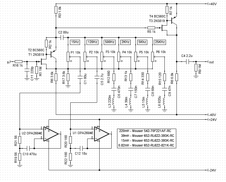
Mouser Stock Numbers for the other four bands are included as an example and as help for those too lazy to even do a quick search there, however they are not necessarily the best choices, just what I could find and which looked okay. The circuit is adjusted to account for the inductor DCR for the items listed.
As these inductors do not have closed core they have a tendency to pick up stray fields. Custom made units on a pot core may be better and one could certainly make the whole set.
The Curves and other performance remains essentially unchanged, as before I have included the Tina-Ti simulation file... The use of Op-Amp's for the Gyrators is necessary (if undesirable), in the simulator at least, as using the same compound Fet/BJT leads to an overall level boost and wrong Q.
The OPA2604 shown here is really just a stand-in, use whatever works for you. The Op-Amp's need more current capability than anything else... Video Op-Amp's are probably a good choice, but can be problematic to stabilise. Adjust rail voltages as needed for the Op-Amp's of choice.
Ciao T
Please continue working up your FET & inductor solution. I've got a stash of suitable inductors leftover from the old days when I had an Auditronics 36 Grand mixing console. The EQ in that console was the reason that I kept it so long. I still have a stash of parts hoarded away. I have stash of FETs as well. If you complete the design I will be sure to build it.
Well, not much else to add really. I don't think I have time to create a PCB and to get further on parts selection.
Attached the version with gyrators for the two LF bands where mouser does not stock suitable inductors.
Mouser Stock Numbers for the other four bands are included as an example and as help for those too lazy to even do a quick search there, however they are not necessarily the best choices, just what I could find and which looked okay. The circuit is adjusted to account for the inductor DCR for the items listed.
As these inductors do not have closed core they have a tendency to pick up stray fields. Custom made units on a pot core may be better and one could certainly make the whole set.
The Curves and other performance remains essentially unchanged, as before I have included the Tina-Ti simulation file... The use of Op-Amp's for the Gyrators is necessary (if undesirable), in the simulator at least, as using the same compound Fet/BJT leads to an overall level boost and wrong Q.
The OPA2604 shown here is really just a stand-in, use whatever works for you. The Op-Amp's need more current capability than anything else... Video Op-Amp's are probably a good choice, but can be problematic to stabilise. Adjust rail voltages as needed for the Op-Amp's of choice.
Ciao T
Attachments
Hi,
Checked a few more things.
Using a CCS (ideal) for the output follower tail increases THD mildly by increasing H2, but reduces higher order content, this is more pronounced with loads far greater than 10K.
The Resistor between base and Emitter of the BJT in our Inverted Fetlington shows also some sensitive re. HD. Increasing the value 3.3K shows a minimum of higher order HD at the cost of 6dB more H2.
I would be reluctant to trust a simulator implicitly on small details like that, so the circuit would have to be build and measured to confirm the sim and I suspect optimum values will be quite a bit different.
Ciao T
Well, not much else to add really.
Checked a few more things.
Using a CCS (ideal) for the output follower tail increases THD mildly by increasing H2, but reduces higher order content, this is more pronounced with loads far greater than 10K.
The Resistor between base and Emitter of the BJT in our Inverted Fetlington shows also some sensitive re. HD. Increasing the value 3.3K shows a minimum of higher order HD at the cost of 6dB more H2.
I would be reluctant to trust a simulator implicitly on small details like that, so the circuit would have to be build and measured to confirm the sim and I suspect optimum values will be quite a bit different.
Ciao T
Those who would like a detailed explanation of how this circuit basically works, or how an opamp version would look like, could have a look at this excellent site :
Bandcut and Bandboost - Series LCR and Pot
Bandcut and Bandboost
Bandcut and Bandboost
http://www.ecircuitcenter.com/Circuits/op_bandcut_boost/op_L_simulate_boost_cut.htm
Some, however, swear by a pure passive approach, even though it is cut only.
Google e.g. White Instruments Model 4420.
Patrick
Bandcut and Bandboost - Series LCR and Pot
Bandcut and Bandboost
Bandcut and Bandboost
http://www.ecircuitcenter.com/Circuits/op_bandcut_boost/op_L_simulate_boost_cut.htm
Some, however, swear by a pure passive approach, even though it is cut only.
Google e.g. White Instruments Model 4420.
Patrick
Hi,
The White 4420 was meant to EQ resonances, feedback etc. in PA systems, hence it is deigned cut only.
However technically speaking a pure passive EQ can offer boost, the old Langevin Model 252A for example was a purely passive 7-Band Graphic EQ that could offer boost.
However, the penalty you incur is static attenuation.
My original idea was to actually just make a passive EQ (not exactly Langevin Style, but related) and let everyone add their favourite buffers (input) and Gainstages (output), however this is only a distant third.
Once we have finalised the Filters the circuit can indeed be applied with a wide range of electronics, Op-Amp's, discrete Op-Amp's, Tube Op-Amp's, discrete solid state (as shown) or Tubes set as analog's to the Fets.
Ciao T
Some, however, swear by a pure passive approach, even though it is cut only. Google e.g. White Instruments Model 4420.
The White 4420 was meant to EQ resonances, feedback etc. in PA systems, hence it is deigned cut only.
However technically speaking a pure passive EQ can offer boost, the old Langevin Model 252A for example was a purely passive 7-Band Graphic EQ that could offer boost.
However, the penalty you incur is static attenuation.
My original idea was to actually just make a passive EQ (not exactly Langevin Style, but related) and let everyone add their favourite buffers (input) and Gainstages (output), however this is only a distant third.
Once we have finalised the Filters the circuit can indeed be applied with a wide range of electronics, Op-Amp's, discrete Op-Amp's, Tube Op-Amp's, discrete solid state (as shown) or Tubes set as analog's to the Fets.
Ciao T
BTW could it be that C10 should be swapped with R21, and C12 with R20 ?
See Fig. 7 of :
Audio Designs With Opamps
Patrick
See Fig. 7 of :
Audio Designs With Opamps
Patrick
Hi,
No, of course not. What RE shows as usual is not 100% correct (that comes from copying others). The circuit using what is basically a Sallen Key Filter does not behave correctly like a "virtual inductor". It "kind of works", but is not a correct alternate to using an inductor.
Ciao T
BTW could it be that C10 should be swapped with R21, and C12 with R20 ?
See Fig. 7 of :
Audio Designs With Opamps
No, of course not. What RE shows as usual is not 100% correct (that comes from copying others). The circuit using what is basically a Sallen Key Filter does not behave correctly like a "virtual inductor". It "kind of works", but is not a correct alternate to using an inductor.
Ciao T
Hi,
Not much really. I looked.
What I was thinking originally was that there was no way to get sensible agreement on "Op-Amp's" vs. "Discrete" vs. "Fet" vs. "Bjt" vs. "Tube".
One Man's "best sound ever" seems anothers "worst sound ever"'.
I was thinking it more constructive to bypass all of this tosh and instead have a pure passive tone control, with the kind of attenuation that comes as price of having "Passive Boost", the kind I called MPPJBTS in the original thread. This allows everyone to pick their own poison and use whatever they want as input buffer and as output "re-gain" amp.
Manley's "massive passive" EQ for example uses an Op-Amp as input buffer and a tube circuit as re-gain amplifier and for output buffering.
So really, for the active side anything goes...
Anything Goes
But it seems that expecting today's DIY'ers to work out (or select from the existing body of work) a buffer and an around 20dB - 30dB linear Amp in their favourite technology (or to type xxxmH into the search at mouser or digikey) is asking too much.
So this ended up being the "ZEQ" (ZenEQ) instead, which is pretty much close to a buildable project (add powersupplies - Salas-Shunts anyone?).
Substituting the Fet's with tubes and scaling impedances by a factor 10 would turn this into the "HEQ" (HotEQ) with a 10dB noise penalty...
Ciao T
So what exactly do you have in mind ?
Not much really. I looked.
What I was thinking originally was that there was no way to get sensible agreement on "Op-Amp's" vs. "Discrete" vs. "Fet" vs. "Bjt" vs. "Tube".
One Man's "best sound ever" seems anothers "worst sound ever"'.
I was thinking it more constructive to bypass all of this tosh and instead have a pure passive tone control, with the kind of attenuation that comes as price of having "Passive Boost", the kind I called MPPJBTS in the original thread. This allows everyone to pick their own poison and use whatever they want as input buffer and as output "re-gain" amp.
Manley's "massive passive" EQ for example uses an Op-Amp as input buffer and a tube circuit as re-gain amplifier and for output buffering.
So really, for the active side anything goes...
Anything Goes
An externally hosted image should be here but it was not working when we last tested it.
But it seems that expecting today's DIY'ers to work out (or select from the existing body of work) a buffer and an around 20dB - 30dB linear Amp in their favourite technology (or to type xxxmH into the search at mouser or digikey) is asking too much.
So this ended up being the "ZEQ" (ZenEQ) instead, which is pretty much close to a buildable project (add powersupplies - Salas-Shunts anyone?).
Substituting the Fet's with tubes and scaling impedances by a factor 10 would turn this into the "HEQ" (HotEQ) with a 10dB noise penalty...
Ciao T
Hi,
Series connected constant impedance T-Network EQ's. Very complex jiggery pokery. Similar to the equally legendary "Motown" EQ.
Another one to look at google-eyed is the original eckmiller fader, like the W88, this is a 72-Pole Fader (linear, not rotary) including physological frequency response correction. If the contacts where clean you could gainride# on these faders like nothing else I know.
They REALLY "don't make like that anymore"...
Those old original "Pro" pieces are true marvels to behold and their plain looks non-withstanding, they make most "High End" look decidedly under-engineered.
Ciao T
# Gain-riding - the process of manually compressing a recording, by boosting level in quiet passages and cutting it for loud ones, this way relative dynamics are preserved. Needs an engineer that can read the score and rehearse with orchestra and conductor or with the ensemble. Yields a compressed master-tape or direct cut...
I have searched but cannot find any info on the Langevin passive EQ circuit.
I presume it is in series, and could not quite figure out (yet) how to do one in parallel.
Any hints ?
Series connected constant impedance T-Network EQ's. Very complex jiggery pokery. Similar to the equally legendary "Motown" EQ.
Another one to look at google-eyed is the original eckmiller fader, like the W88, this is a 72-Pole Fader (linear, not rotary) including physological frequency response correction. If the contacts where clean you could gainride# on these faders like nothing else I know.
They REALLY "don't make like that anymore"...
Those old original "Pro" pieces are true marvels to behold and their plain looks non-withstanding, they make most "High End" look decidedly under-engineered.
Ciao T
# Gain-riding - the process of manually compressing a recording, by boosting level in quiet passages and cutting it for loud ones, this way relative dynamics are preserved. Needs an engineer that can read the score and rehearse with orchestra and conductor or with the ensemble. Yields a compressed master-tape or direct cut...
Hi,
What I show is meant to be strictly a "tone control".
System integration is up to the user.
As it is unity gain adding a bypass relay is not a big deal. As there is a fair bit of interactivity and level shift when using this we may also want to add a +/- 6dB Gain trim (again, like in the Palette) and possibly a Line Gainstage after or before.
But again, there are so many options to choose from for any of these blocks, that I'd rather leave it to the user... After all, this is DIYAUDIO.COM and not BIYAUDIO.COM (aka audiogon).
Ciao T
Do you expect this East German Cello Clone to be used in the tape loop or to sit between the preamp and amp? If the latter, some may want a defeat switch/relay.
What I show is meant to be strictly a "tone control".
System integration is up to the user.
As it is unity gain adding a bypass relay is not a big deal. As there is a fair bit of interactivity and level shift when using this we may also want to add a +/- 6dB Gain trim (again, like in the Palette) and possibly a Line Gainstage after or before.
But again, there are so many options to choose from for any of these blocks, that I'd rather leave it to the user... After all, this is DIYAUDIO.COM and not BIYAUDIO.COM (aka audiogon).
Ciao T
May I propose the following changes to your schematics in post #18, just for discussion :
T1+T2 -> 2SK369BL
R6 -> 2SK369BL matched Idss to above
R7 -> 1.8k
T3+T4 -> 2SJ74 BL with 1.8k degeneration.
R8 -> 2SK170BL with matched Idss ot 2SJ74.
C4 removed.
Negative rail to -20V.
The 2SK170 can also be conveniently turned into a servo.
Result : All JFET, no couplung caps, improved PSRR to +ve rail.
Please feel free to comment / criticise.
Patrick
Last edited:
Hi,
Yes, I would in principle agree with these, however it will produce less linearity and more parasitic capacitance than what I show, while using parts that for many potential builders are hard to find.
BTW, R6 should be 1.8K in series with the 2SK369V (or better, halves of the LSK389), so both sections have the same voltage across them.
However my take allows pretty much any generic medium Gm RF Fet (BF244/245, 2N38XX and so on) to be combined with a decent Small Signal PNP Transistor, no selection needed and to get good results.
If we arrange the PCB right we can just fit the "good" Fets you and I have, leave the PNP off and short the resistor and enjoy our five to tenfold THD increase and sound truly of "one fet clapping". I'm sure it will actually sound better.
The CCS could theoretically be beneficial if we have too much noise on the negative line (positive PSRR remains near zero), but I think we can afford decent supply regulation.
This still needs a buffer (output absolutely must be buffered somehow/somewhere) and does not strike me as all that horrorshow.
A servo is just a different place for the coupling cap, if it does it's job properly it will not allow lesser quality capacitors. DC coupling = no capacitor sound is almost always an illusion, not actuality, often the reverse is true.
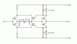
Here what I have been considering (Principle only, precise circuit would look different...) to get rid of the evil coupling capacitors:

This will need a servo of course.
Anyway, surprise, surprise, in almost any relevant metric we have performance comparable to the much simpler original. PSRR is much better, but we where going to a decent set of supplies, right?
If we really want guru cred we would make it rail symmetrical with K170/J74 and impossibly tight selection requirements. At least we would reduce HD this way...
So, all long considered.
I'm not rejecting it, but I do not feel that the results will necessarily be better than the basic one above, but complexity, trouble shooting requirements and all sorts of stuff goes way up, as does cost.
All of this in my view makes it worse as a DIY project, though it has a better chance to be listed somewhere as "fiendishly clever circuitry that should sound great but which somehow did not get to work, more luck to you".
And what would we have achieved for all this extra complexity?
We moved the Evil Coupling Capacitor from a visible place (Horror, there is a coupling capacitor - it cannot be high-end) to one where it is less visible (servo) but where it's sonic damage can be amplified... Worse, while people MAY shell out for something decent for coupling cap, they never do for the servo one.
It seems to me a poor trade-off, overall. But others may feel different.
I do not pursue simplicity for it's own sake, so I'm happy to notch that up, way up, if someone has a better answer to:
"Why?"
than
"To remove the evil coupling capacitor"
because neither do I pursue complexity for it's own sake, I want real benefits from increasing it.
Ciao T
May I propose the following changes to your schematics in post #18, just for discussion :
T1+T2 -> 2SK369V
R6 -> 2SK369V matched Idss to above
R7 -> 1.8k
Yes, I would in principle agree with these, however it will produce less linearity and more parasitic capacitance than what I show, while using parts that for many potential builders are hard to find.
BTW, R6 should be 1.8K in series with the 2SK369V (or better, halves of the LSK389), so both sections have the same voltage across them.
However my take allows pretty much any generic medium Gm RF Fet (BF244/245, 2N38XX and so on) to be combined with a decent Small Signal PNP Transistor, no selection needed and to get good results.
If we arrange the PCB right we can just fit the "good" Fets you and I have, leave the PNP off and short the resistor and enjoy our five to tenfold THD increase and sound truly of "one fet clapping". I'm sure it will actually sound better.
The CCS could theoretically be beneficial if we have too much noise on the negative line (positive PSRR remains near zero), but I think we can afford decent supply regulation.
T3+T4 -> 2SJ74 BL with 1.8k degeneration.
R8 -> 2SK170 with matched Idss ot 2SJ74.
C4 removed.
Negative rail to -20V.
This still needs a buffer (output absolutely must be buffered somehow/somewhere) and does not strike me as all that horrorshow.
A servo is just a different place for the coupling cap, if it does it's job properly it will not allow lesser quality capacitors. DC coupling = no capacitor sound is almost always an illusion, not actuality, often the reverse is true.
Here what I have been considering (Principle only, precise circuit would look different...) to get rid of the evil coupling capacitors:
This will need a servo of course.
Anyway, surprise, surprise, in almost any relevant metric we have performance comparable to the much simpler original. PSRR is much better, but we where going to a decent set of supplies, right?
If we really want guru cred we would make it rail symmetrical with K170/J74 and impossibly tight selection requirements. At least we would reduce HD this way...
So, all long considered.
I'm not rejecting it, but I do not feel that the results will necessarily be better than the basic one above, but complexity, trouble shooting requirements and all sorts of stuff goes way up, as does cost.
All of this in my view makes it worse as a DIY project, though it has a better chance to be listed somewhere as "fiendishly clever circuitry that should sound great but which somehow did not get to work, more luck to you".
And what would we have achieved for all this extra complexity?
We moved the Evil Coupling Capacitor from a visible place (Horror, there is a coupling capacitor - it cannot be high-end) to one where it is less visible (servo) but where it's sonic damage can be amplified... Worse, while people MAY shell out for something decent for coupling cap, they never do for the servo one.
It seems to me a poor trade-off, overall. But others may feel different.
I do not pursue simplicity for it's own sake, so I'm happy to notch that up, way up, if someone has a better answer to:
"Why?"
than
"To remove the evil coupling capacitor"
because neither do I pursue complexity for it's own sake, I want real benefits from increasing it.
Ciao T
Attachments
Hi,
Incidentally, as we have several 100 matched 2SK170/2SJ74 pairs in stock, for my own use I'd probably build this:
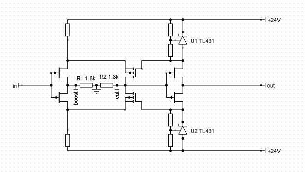
But for most this will not be much of an option, given the ease of acquisition of matched pairs of genuine Toshiba complementary Fets...
Ciao T
Incidentally, as we have several 100 matched 2SK170/2SJ74 pairs in stock, for my own use I'd probably build this:
But for most this will not be much of an option, given the ease of acquisition of matched pairs of genuine Toshiba complementary Fets...
Ciao T
Attachments
Patrik,
The output buffer can be omitted under two conditions:
1) The load on the output is infinite (in other words the inputs of the circuits following are reliably buffered)
2) The load on the output is clearly defined, unchanging and designed into the circuit as part of the output load.
Under all other circumstances a buffer is required.
Ciao T
Something like post #37 was also what I had in mind when going for complementary all FET, though I do tend to consider the output buffer not an absolute necessity.
The output buffer can be omitted under two conditions:
1) The load on the output is infinite (in other words the inputs of the circuits following are reliably buffered)
2) The load on the output is clearly defined, unchanging and designed into the circuit as part of the output load.
Under all other circumstances a buffer is required.
Ciao T
- Home
- Source & Line
- Analog Line Level
- Cello Palette Style EQ Design (was High End Tone Control)...
