I didn't think of the reeds, but the (superficious) similarity with the cello mechanic... those look so DIY (but of outstanding quality, mind you) I naively didn't even think of it being a challenge... haha.The reed approach...
You are back in Seiden price territory - and doing it yourself.
…construction of the Cello switches? Multiple ball races, custom contact assembly, in fact everything custom other than the resistor string - they are a thing of Swiss watch beauty. Trying to replicate them would be alas a fool's errand.
So I had another look at them, and they do look fabulous, but—I don't quite get it: Where do the resistors go? (connected on the other side), and what is this t-connection opposite of the input?

Wow, well with eight 15” woofers I can see how you can easily tell the difference in the low end! Those are impressive speakers, I have always liked the classic JBL’s. Thanks ticknpop for the kind words of recognition. I hope my work helped your equipment sound better. You now have a very nice SAE EQ!Much more resolving, especially in the bottom end where it has much more detail and control. Use it on 4 of JBL 4350 black plywood clones we have at work - thanks for your pioneering work on power supply noise.
We cheated and used 2 of the 18 inch 2245 then the 2202 12 inch mid, and 2395 lens 2441 Alnico and 2405. Not furniture finish , but still sound nice in 1500 sq feet shopWow, well with eight 15” woofers I can see how you can easily tell the difference in the low end! Those are impressive speakers, I have always liked the classic JBL’s. Thanks ticknpop for the kind words of recognition. I hope my work helped your equipment sound better. You now have a very nice SAE EQ!
I've deconstructed an image of what must have been an output level control, and confirmed that it was a 20k (20,005.12 actual) pot, with the first two steps from zero 5dB, the next 5 steps 2dB, and the rest 1dB. That corresponds to the steps set out in Burwen's design study "+10 to -40 dB in 1 dB steps , -42, -44, -46, -48, -50, -55,-60, OFF"
In Burwen's original design, the total resistor value is the somewhat odd value of 4060 ohms, and in the Audio Palette (as mentioned above) 20k.
In Burwen's original design, the total resistor value is the somewhat odd value of 4060 ohms, and in the Audio Palette (as mentioned above) 20k.
Hi all,
Yes, the original palette design was insane.
I'm familiar with seiden and their switches, very good.
Now again, speaking from personal experience and preference ONLY, I the original palette is overly precise.
Of course true " Hai Ente" (Shark Duck - you need German and High End Audio discipline to find that funny) is all about conspicuous consumption and ridiculous levels of over engineering.
Back in the real world, I tend to adjust EQ when tuning products by 0.5dB steps in the Midrange, more at higher and lower frequencies (see Robinson/Dodson, Fletcher/Munson et al).
I think +/- 5.5dB in 0.5dB steps are fine for the Midrange, 24 position Elma can do that, bigger straps moving outwards too.
IF one really needs smaller steps, add a toggle to switch range between full and half range/step.
A true copy with seiden switches can be build of course as well, it will still be fairly modest in cost.
I do not know if the special "S" track Vishay/Sfernice cermet track pots used in the "cheap" palette can still be found, even in the 90's they already were fairly rare and dear.
Don't expect a cheap Chinese pot or even the 16mm motorised Alps used by Schiit in their top ranking unit to sound anywhere near as good as the Sfernice cermets (I know them all). Now an Alps 24-Way switch, with good MELF resistors, I think it will be a smidgen ahead of a Vishay/Sfernice Cermets pot.
Everything is a compromise.
I started DIY back in what was East Germany mainly to make with what I could get something I actually wanted to have and could not get (might add afford, but that was more a question of ridiculous price western imports).
So in my books absolutely slavish copies are something only Chinese do. Smart people lift the essentials and find a way to realise those in "their way".
I ma in no way dumping on Cello, Schiit or anyone else.
I just feel that limited budget but aiming at high objective and subjective sound quality close or beyond "Cello" and exceeding Schiit is doable and in my books that is where I think it gets interesting.
Focus on the essentials, deliver them with the simplest, most transparent design, sacrificing fluff a commercial product needs. If you cannot be transparent, make sure the "nontransparent" aspects "sound good".
That's it. End of sermon.
Thor
Agree with all of that!
Now here is an odd thing. The 20k pot I deconstructed from images did what Burwen (and the Cello output control markings and operator's manual) says.
But the other image I've done provides precisely the same attenuation law - but is Burwen's value of 4060 ohms (4061.19 actual).
So for some reason, Cello either decided to adopt two values for the output pot at different times.
The 4060 ohm image is here https://skyfiaudio.com/products/cello-audio-palette-eq-preamp-with-power-supply-rare
And the 20k image is from here https://kaitori-audiodripper.jp/cello-audio-palette-used-kaitori
OK - here are the results. The resistors are in a series chain, and the switch wiper selects the tapping point in the chain. The attenuation results are identical - two steps of 5dB, five of 2dB and the remaining at 1dB. Although I've taken nominal values, all resistors used are mainly Dale, and are nominally 1% tolerance. However as someone who uses these in other designs, 1% is closer to 0.1% in practice.
Yes - I know that in the worst case there are 29 resistors in series from the wiper to ground and 29 to the signal input. But it seems that no one who has used the Audio Palette has noticed any sonic disadvantage to this arrangement.
Yes - I know that in the worst case there are 29 resistors in series from the wiper to ground and 29 to the signal input. But it seems that no one who has used the Audio Palette has noticed any sonic disadvantage to this arrangement.
Attachments
Sawyers.
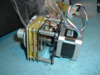
I have the resistor values somewhere for all the xx position switches used in their products. Have/had a bunch of parts for the switches also. they used special plating on the switch pc boards and a special wiper. Have some pics that I can post. Made up a vew volume attenuators and added a stepping motor on the back to enable remote control.
Regarding what to use for bass cut/boost "controls" - have a (n expensive) ball using switches. The Alpha dual pots I've used on mine work just fine. Both channels track over their useful range within fractions of a dB and once I figured out the dial calibration/markings, seem repeatable within a couple tenths of a dB.
Charles
Hi Charles
I'm certainly not intending to replicate the glorious custom switches - but (as you have probably realized!) I really enjoy getting under the skin of something as classic as the Audio Palette. So if and when you have the time to seek out the resistor values, and anything else you have lurking, it would be very much appreciated.
But like you I will pretty much certainly go for dual gang pots in my build. Either Alpha or Bourns.
Cheers
Craig
Using my spice model for the Audio Palette, I've figured out the resistor chain for the 15Hz filter, which uses a 10k resistor chain. This is attached. It is based on E96 resistor values, and the boost curves are attached. The nominal step value is 1dB, which it meets to about +/-0.03dB, apart from a couple at +0.06dB and one at +0.15dB
The actual resistor values used by Cello might be slightly different, but this design is very close in overall response.
Craig
The actual resistor values used by Cello might be slightly different, but this design is very close in overall response.
Craig
Attachments
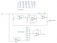
The attached is the basic filter configuration I'm using in the analysis. P2 is the stepped control. The wiper is buffered by IC1 and then fed into the bandpass filter IC2. This is where I deviate from both Burwen's arrangement and the Audio Palette based on it. In both of these, the filter outputs are summed into the non-inverting pin of IC3. With an inverting summer everything can be designed straightforwardly. The difficulty with a non-inverting summer is calculating the resistor values; this is what the analysis looks like https://masteringelectronicsdesign....f-the-summing-amplifier-with-n-input-signals/, and is candidly pretty messy.
So what I have done instead is to close the filter loop with an additional opamp, with the output of the bandpass filter feeding the non-inverting input of IC3 directly. In addition each bandpass filter has two resistors on the input. This gives the correct response (see the 15Hz and 25kHz responses above). The output of each filter block is summed into the inverting input of IC4 with identical resistors. IC5 is necessary to give an overall unity gain with all filters set to flat. The IC5 summing resistor needed is Rsum/(n-1) where Rsum is the 1k filter summing resistor. There are 6 of those, so it needs a 200 ohm resistor to set the flat gain to 1 (ie 0dB).
This is not a particularly elegant arrangement - it needs three opamps per filter block. The elegance of the Palette Preamplifier, based on the National apps book, is that only one opamp is needed per filter cell.
Anyway, the overall scheme is shown in the attached schematic, along with component values. The capacitance values are the same as in the Audio Palette, other than the 25kz filter, in which I have adjusted things to further reduce noise.
Craig
Attachments
This is not a particularly elegant arrangement - it needs three opamps per filter block. The elegance of the Palette Preamplifier, based on the National apps book, is that only one opamp is needed per filter cell.
This kinda reminds me of the NitePro 3D. Much easier and not as precise as the Palette. But also parallel summing.
I did think of it as interesting enough to re-engineer into a palette style EQ...
Thor
Interesting approach, Thor. The filter blocks are not second order.
With second order filters (like the Audio Palette and Palette Pre) you can control the gain and Q. The gain dictates the maximum boost/cut, and the Q determines the width. So the Q of the 25Hz and 25kHz are about 2, and the block gains determine the +/-29 and +/-24 dB respectively. Other topologies that can give second order responses are state variable and biquad arrangements - although these are also op-amp hungry.
As I said, the filter elements in the NitePro 3D are all first order. So the bandpass filters are made up of a first order low pass and a first order high pass. So you cannot adjust the Q.
That is not to detract from the rather elegant simplicity of the NitePro 3D, and the positive reviews regarding sound quality. The only criticisms I've read (Googling following your post) is that there are two independent channels, not a ganged stereo arrangement, and no center detente.
The really elegant second order filter in which Q and gain are designable is the Palette Preamp, where a single opamp per filter is all you need.
Craig
Last edited:
The really elegant second order filter in which Q and gain are designable is the Palette Preamp, where a single opamp per filter is all you need.
I would say that the really elegant approach is LC, where no active components are required and Frequency, Q and impedance can be freely selected.
Or DSP if we use digital sources and digital (switching) amplifiers anyway.
One is for the extremist analog purists who would also take a transformer volume control over an active preamp and the second for the "Digital über alles in der Welt" purists.
Maybe one day I will issue a "Digital Palette Preamp" with SPL calibrated physiologically corrected playback volume control (really works that one*), palette style digital remastering EQ, dynamic Expander, stereo sound field control, all with mastering studio grade DSP routines.
Output as PCM and optional PDM/DSD for direct amplification via GANFET DSD256 power amplifiers.
Thor
* The ifi Aurora all in one has a German braunbuch studio required physiologically corrected playback level control (not loudness) in the analogue domain.
As the speakers, amps, source etc are known and most streaming services etc. normalise gain to -14 (dB) LUFS (+/- a few dB) and I assumed 3m listening distance under normal use cases, it all falls into place.
A lot of audiophile reviewers were amazed how with the Aurora the bass doesn't disappear as volume is lowered.
But it's hard to correctly integrate into (say) an analogue preamp that will be used with random sources, amplifiers and speakers.
There it's almost impossible to make things fall into place without input and output level trim and carefully setting playback SPL vs Volume and trimming the input gain so average = -14 LUFS...
A good physiological corrected volume control I feel reduces the perceived need to EQ tracks.
We've talked about the pros and cons of inductors as an electrical component. Modelling shows them to be fantastic ideal components; the practical reality is very different.
Like any other component, inductors need to be specified correctly for the application.
Even op-amp's, resistors and capacitors are far from ideal.
If we want ideal, only a fully digital system designed by people who understand that good measurements and theory does not equal good sound can deliver this. It is certainly the future.
If we wish to dwell, wallop, get buried in the analogue past, why insist on a skinny latte with soi milk, if you can have it full fat, extra brown sugar and whipped cream with caramel on top for your effort?
Just my logic. There are absolutes, but even those are relative.
Give me pleasure over being right, give me pleasure over accuracy. Heck, my girlfriend is 23 and super hot, but she still looks more sexy and desirable (think Crissy Teign, no sh!t) if I take my accurate glasses off and add a little "soft focus".
If I drop my "accuracy" glasses that make me see every tiny skin flaw, she is much more pleasureable to be with for me.
In other words, focus on what is right not on what might be (or not be) wrong.
Makes me a happy chappy fer sure. I look like a Cheshire cat all the time. And yes, my mostly BYO "Beach (bum) house" sound system, for all it's failings makes me and her happy to drop tunes and turn it up.
Of course, that's just me. And my life.
Thor
Palette switch info
The resistor values around the periphery of the xxHz pdf's relate to the position where they were to be mounted on the switch's PC bord - between switch poles.
Not all 59 poles were used for certain switches. Some were 49 poles. Had 2 different "stop plates" made up for the particular switch. Most switches were single deck. A few were 2 deck,
Picture is of a 2 deck attenuator I made up with stepper motor control - with the help of John Chapman.
Attachments
Last edited:
- Home
- Source & Line
- Analog Line Level
- Cello Palette Style EQ Design (was High End Tone Control)...