No, pin1 of the XLR is really a ground - to maintain some degree of restraint over the common mode voltage. The shell is the shield.
With a balanced signal and with the two pots on the one channel also balanced there will be no net current returning to pin1. But of course no pot is actually that good in terms of matching so pin1 comes to the rescue to remedy the slight imbalance in practice.
With a balanced signal and with the two pots on the one channel also balanced there will be no net current returning to pin1. But of course no pot is actually that good in terms of matching so pin1 comes to the rescue to remedy the slight imbalance in practice.
No, pin1 of the XLR is really a ground - to maintain some degree of restraint over the common mode voltage. The shell is the shield.
Really what I ment was that the ground is there just as an electric potential link (connect equipments grounds, shields, cases, power supply capacitors protection). Is not ment to carry/return SIGNAL. It probably can, but is not supposed to.
It is a quad. Therfore four potentiometers. Each has a connection to the ground that is not supposed to be for signal return.It is one pot (quad Alps) for both channels actually. Does that make a difference?
That's the problem with the ballanced equipment volume adjustment.
Last edited:
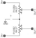
There is more than one way to employ a quad potentiometer for balanced volume control. I think it would be easier to recommend an approach as soon as the applied schematic was clear.
I've drawn one for you. I assume that your question is regarding the wire with a question mark?
Two things are to be determined:
• wether the connection is to be made at all,
• wether it is only a ground or also a shield connection.
One thing is for sure, though: using pin 1 for one function while using the shield connector for another (and not somehow connecting those two) is not a viable option.
Cheers,
Sebastian.
Attachments
Really what I ment was that the ground is there just as an electric potential link (connect equipments grounds, shields, cases, power supply capacitors protection). Is not ment to carry/return SIGNAL. It probably can, but is not supposed to.
Right, I got ya and I agree. If the pot is truly balanced (and the source is a true balanced signal) then it won't (to a first order).
I think if we want to be concerned about unbalancing the ground then we either need to
remove the ground connection totally and accept output unbalancing, or
use the pot just as a variable resistor with series pads (and accept a lower than 0dB minimum attenuation), or
go active, or finally
use stepped attenuators with precision resistors as you suggest Andrew
There is more than one way to employ a quad potentiometer for balanced volume control. I think it would be easier to recommend an approach as soon as the applied schematic was clear.
I've drawn one for you. I assume that your question is regarding the wire with a question mark?
Two things are to be determined:
• wether the connection is to be made at all,
• wether it is only a ground or also a shield connection.
One thing is for sure, though: using pin 1 for one function while using the shield connector for another (and not somehow connecting those two) is not a viable option.
Cheers,
Sebastian.
Thanks Sebastian, that's exactly what I mean. The question is mainly regarding the screen connection (pin 1 on the XLR) although of course the "chassis" connection of the XLRs is also important.
/U.
Well, as Andrew already said pin 1 of the incoming interconnect is always connected to the shield. After all, a balanced interconnect is a twisted pair, which is a two wire line. If pin 1 wouldn't connect to the shield, what else would it go to? ")
This poses the problem of separating the center point between the pots from the dirty shield currents.
One viable option really is to not connect it to anything. Wether this option is applicable to your case entirely depends on the equipment you intend to connect (and wether it's input is truly balanced). But Andrew is also right in raising the question wether the precision of an ALPS RK27 would be sufficient to maintain balance within your setup.
Essentially, the most important improvement of balanced execution (in favor of an unbalanced preamp) is the larger common-mode rejection in balanced input stages. Another improvement is a 6dB increase in dynamic range, as the balanced line driver inside the signal source has a differential gain of 6dB without also increasing noise in the same way.
A common misconception about balanced wiring is that it's advantages stem from the increase in total drive voltage, when in reality they come from the equal impedance on both polarity sides, all the way from transmitter to receiver. Thus, all the hassle with the balanced preamp is only worth it if the common-mode rejection isn't worsened and the penalty of using the RK27 doesn't cost more than 6dB in dynamic range (overall).
Cheers,
Sebastian.
In order to keep the symetry, you will need something like this (R2 being between two pins of the variable potentiometer):
An externally hosted image should be here but it was not working when we last tested it.
No, pin1 of the XLR is really a ground - to maintain some degree of restraint over the common mode voltage. The shell is the shield.
This is incorrect.
The XLR pin #1 is shield only. This shield connection should be direct to the chassis.
The shell is also shield only, but often no cable wire is connected to the shell.
While the audio circuit ground is usually connected to the chassis, this does not make the shield part of the audio circuit.
The circuit that "SoNic_real_one" posted is correct.
The XLR pin #1 is shield only.
Nope, the pin1 connection is to the drain wire. A shield is optional on the cable - most have it but its not essential.
This shield connection should be direct to the chassis.
Yes - but the pin1 connection should really be to the star earth on the chassis, not the chassis at the point of entry. The shield though goes to the chassis at the entry point to ensure lowest possible series inductance. Whereas for pin1 we want the lowest possible induced common mode voltage.
The shell is also shield only, but often no cable wire is connected to the shell.
Sure - there's no cable because its a mechanical connection on the plug in plugs I've wired up.
While the audio circuit ground is usually connected to the chassis, this does not make the shield part of the audio circuit.
I can't follow what you're saying here. Care to explain what 'part of the audio circuit' means?
If the schematic posted above is not a straight answer, then you picked the wrong hobby.
Sorry, but my original question was/is how to wire this up using a quad Alps pot and if that was possible. Apologies if I have misunderstood the schematic - simple as it may be
/U.
Nope, the pin1 connection is to the drain wire. A shield is optional on the cable - most have it but its not essential.
To me the word "drain" is the wire that is connected to the "shield". So in this case they have about the same meaning.
A shield is optional on the cable - most have it but its not essential.
Yes, this is true.
Yes - but the pin1 connection should really be to the star earth on the chassis, not the chassis at the point of entry. The shield though goes to the chassis at the entry point to ensure lowest possible series inductance. Whereas for pin1 we want the lowest possible induced common mode voltage.
No, this is incorrect. XLR pin1 should be connected directly to the chassis, with as short a wire as practicable. (do you need references?)
Quote:
The shell is also shield only, but often no cable wire is connected to the shell.
Sure - there's no cable because its a mechanical connection on the plug in plugs I've wired up.
This is incorrect. Measure a plug.
I can't follow what you're saying here. Care to explain what 'part of the audio circuit' means?
I mean, the audio circuit will function with no connection to the cable shield.
XLR pin1 should be connected directly to the chassis, with as short a wire as practicable. (do you need references?)
If you do this when there's more than one XLR (for example even a stereo pair) you'll end up with currents flowing through the chassis. Do you want this? Also what to do when the chassis is non-conductive?
This is incorrect. Measure a plug.
What measurement can I take which will show (or not) a mechanical connection?I mean, the audio circuit will function with no connection to the cable shield.
Oh in that case, yep I agree, it will.
- Status
- This old topic is closed. If you want to reopen this topic, contact a moderator using the "Report Post" button.
- Home
- Source & Line
- Analog Line Level
- Grounding in balanced passive pre?