Hello,
I'm planning to build myself a very simple pre-amplifier. Just for home use but I'd like to try and do a good job.
I currently run my DAC directly into my power amp. I use a couple of passive attenuators to control the maximum output and then I'm using the digital volume control on my Squeezebox Touch for small adjustments. I have several different attenuators for big steps in volume level but the setup is not really ideal and I've noticed some small differences depending upon what resistor values I choose for the attenuators.
So the idea is really a buffered volume control more than a fully fledged preamp, with just a single input and output. My plan is to use a couple of op-amps on each channel as an input and output buffer with a volume pot in-between. I'm looking forward to trying out some different configurations and to listen to the difference.
But... the first thing to get sorted is the supply for the preamp.
So the question is:
Is it worth bothering with a battery supply (SLA for example), can this be lower noise?
If I'm going to the trouble of making a charging circuit for the batteries then should I just make a straight regulated supply instead?
With the battery route is it normal to regulate the battery rails or do people just run the op-amps straight from the batteries (with some bypass caps at the ics)?
Do some battery chemistries have lower noise than others (for example there is a lot of chatter about Li-Fe-PO4 batteries)?
Any advice is appreciated!
Thanks, Jack.
Since your design objectives include the minimization of power supply related artifacts, I suggest that you consider an autoformer, which is a completely passive volume control. This could be synergistic with your application for a number of reasons. Intact audio offers a couple of well regarded diy units.
intact audio
intact audio
Passive is OK. BUT, ONLY if you can get the impedances on both sides of the volume control within the range that gives correct loading to all the stages. There are 4 links to consider. The source loading. The volume control input loading. The volume control output loading. The receiver input loading.
This is not easy and it's usually easier, to ensure the correct impedances are available, to use a buffer somewhere in the volume control circuit.
I agree that technically an auto transformer is passive. But there are many impedance and resonance complications in transformer coupling that make it, in my opinion, just as complex as going active. I believe it can be easier to buffer than to use transformer coupling. It will certainly be cheaper to buffer.
Last edited:
Since your design objectives include the minimization of power supply related artifacts, I suggest that you consider an autoformer, which is a completely passive volume control. This could be synergistic with your application for a number of reasons. Intact audio offers a couple of well regarded diy units.
intact audio
Thanks for the reply Ken, I had been considering passive options prior to trying the fixed attenuator route that I have now (which was a bit of a feeler for stepped attenuator). I'll take a look at the intact audio units. However, ideally I'd like to have something versatile with a high input impedance and low(ish) output impedance so that I can change my power amp and fiddle with my DAC and not worry too much about the matching.
Hi Jack,
I've been using an amplifier some years ago that was designed with 2 transistors in the input (voltage amplifier stage) and then a couple of emitter followers for the output stage. The input stage was preceded by a quite low-impedance attenuator coupling and to my ears sounded very relaxed and superbly open - with a wealth of nuances.
It was powered by SLA batteries and is very dependent on component matching (probably due to it's clarity and openness). So for it to sound well you should expect to try out some components for right balance of tonality etc. It's fully class A & single-ended & no-NFB & simple - yet as I mentioned component selection is key.
If that sounds interesting to you I can post a schematic and some hints on how to build it.
Greetings,
Jesper
Hi Jack,
I've been using an amplifier some years ago that was designed with 2 transistors in the input (voltage amplifier stage) and then a couple of emitter followers for the output stage. The input stage was preceded by a quite low-impedance attenuator coupling and to my ears sounded very relaxed and superbly open - with a wealth of nuances.
It was powered by SLA batteries and is very dependent on component matching (probably due to it's clarity and openness). So for it to sound well you should expect to try out some components for right balance of tonality etc. It's fully class A & single-ended & no-NFB & simple - yet as I mentioned component selection is key.
If that sounds interesting to you I can post a schematic and some hints on how to build it.
Greetings,
Jesper
Hi Jesper,
That sounds very interesting. Similar to what I was thinking but with discrete components instead of opamps. I would certainly be interested to have a little more information.
Please can you tell me how you manage the supply side of things? Do you regulate the output from the batteries or use them directly as your voltage rails? What about charging? I was thinking of having a float charger which could be turned on when I'm not using the preamp to top up the batteries.
Please can you tell me how you manage the supply side of things? Do you regulate the output from the batteries or use them directly as your voltage rails? What about charging? I was thinking of having a float charger which could be turned on when I'm not using the preamp to top up the batteries.
Hi Jack,
What I have done in terms of charging the batteries is exactly what you are thinking of. When running my circuitry off a stereo battery supply the current consumption is only ~30 mA so a 7AH 12VDC battery may supply power for this for a very long time (remember that SLAs in general do not like deep discharges. The 7 AH models typically have a comparatively low ESR. I used batteries from Yuasa and Panasonic). I've made a quality supply that can be disconnected via e.g. a contact or a couple of relays.
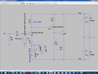
Regarding the circuitry I've attached a jpg file of what it looks like. Please note that this is not a circuitry that I - if I take on my engineering perspective - would design exactly like this. But IMHO it sounds outstanding which is why it is as it is.
Components I used were:
- Roederstein RSX resistors (difficult to get) or carbon block resistors. I guess others may be used - but e.g. Vishays had a quite greyish sound.
- Panasonic HFZ electrolytics (though discontinued now) placed very close to where the power is used. High capacity electrolytics were Nichicon GQ series.
- Panasonic copper foil capacitors 100 nF/50volts (connected in parallel with the HFZs)
- BlackGate FKs. In a particular circuitry these were unmatched in the bass, however, haven't used them widely and they seem to be hard to get at today.
- Elma gold plated attenuator with discrete resistors soldered directly onto the attenuator and a circular copper wire connecting the resistors at the circumference of the attenuator.
- A balsa wood 2-3 mm thick "PCB" where I mounted the components. Audibly, this actually is very important, possibly because it eliminates the dielectric absorption normally found between the copper surfaces/wires on a PCB and the - maybe - epoxy basis. Balsa has a dielectric coefficient very close to that of air. I used a needle to make holes in the balsa where the components go through the balsa.
- Uninsulated copper wires to connect the components. 1mm thickness. Short wire lengths also on the "PCB". Be especially mindful about the wire from C1 & C2. Again no insulation due to dielectric absorption. I'm considering using argentium wires (silver + germanium - see ebay if you're interested) since they do not oxidize and my preliminary listening suggests that it sounds very good.
- WBT connectors
- If I used metal close to the circuitry it was non-inductive (like brass).
- And VERY important. On both the base and emitter pins of the transistors I placed small ferrite beads. This - with sensible layout - very simply eliminates tendencies to oscillation and - as a possitive side effect - audibly makes the music sound more "manifest" and in balance.
- I used 2SC2240 and 2SA 970 transistors. 2SA872 and 2SC1775 may also be used - to my ears they are slightly different though. In general I have found that this type of transistors sound their "best" (open, detailed, tonally in balance) at a quiescent current that is the max current divided by ~13.
- I used 4*12 VDC/7AH SLAs as I found that the transistors (2240/970) sounded best when the emitter to collector voltage was about 18-19 volts. The SLAs charge at ~13.7VDC each when standby charging.
- The low cut off frequency is about 1.6 Hz. And most likely several MHz on the top.
In general a thing to remember with a circuit like this - which IMHO is very transparent - is that most everything matters. So don't use pins or anything to connect wires on the board to the phone RCAs (if you use such). It will be audible. Solder wires on wires etc. No sockets for the transistors either.
I didn't use a servo circuitry as I found that when this circuitry had stabilized it was not necessary (for temperature stabilization connecting the two transistors with a wooden "block" may help. Heavy woods may be better). However, if you use a charger that is switched on and off there may be a bit of DC offset. If you decide to include a servo I suggest you design it to have a very, very low frequency cut off (e.g. 0.05 Hz) and somehow connect it where the trimpot is placed.
The gain is about 36 dBs (88 times).
Please also note that the circuitry has a rather highish output impedance (about 4kohms) which might have an influence if your power amplifier has a low input impedance OR you use long lengths of interconnect cable with high values of C and L. To that end I have added an emitter follower in the schematic which lowers the output impedance to low levels - but I personally would omit it, if your power amp allows for this.
Also the input impedance is quite low. It didn't cause issues in my system but if you need it higher you can replace R8 with e.g. a 2k2 or 4k7 resistor (haven't tried it though). R1 also can be 4k7 if this fits better with an attenuator.
Hope this helps ...
Best wishes for your project - whatever you decide to do ;-)
Jesper
Attachments
Last edited:
Hi Jack,
....
Hope this helps ...
Best wishes for your project - whatever you decide to do ;-)
Jesper
Hi Jesper,
Many thanks for taking the time to send me such a wealth of information. It will take me a little time to study. It has already given me some good ideas about what I might do.
Thanks!
Jack.
Thanks for the reply Ken, I had been considering passive options prior to trying the fixed attenuator route that I have now (which was a bit of a feeler for stepped attenuator). I'll take a look at the intact audio units. However, ideally I'd like to have something versatile with a high input impedance and low(ish) output impedance so that I can change my power amp and fiddle with my DAC and not worry too much about the matching.
The most significant advantage that an autoformer volume control has over a resistive control is the impedance matching aspect. Should the autoformer be set at an -6dB attenuation, it will reduce the output impedance of whatever is driving it by a factor of four (excluding a few parasitics). So, for example, if you have a DAC with an 1k ohm output impedance, the power amp will see an 250 ohm source impedance via the autoformer. In addition, if the power amp has an input impedance of, let's say, 10k ohms, the DAC would see a load of 40k ohms via the autoformer. At an -12dB attenuation the effective source impedance to the power amp would be 62.5 ohms, while the reflected load to the DAC would be 160k ohms. Again, negleting a few parasitic impedance elements, such as coil winding resistance.
Last edited:
- Status
- Not open for further replies.
- Home
- Source & Line
- Analog Line Level
- Advice on a simple preamp