Hi all,
I am very much a Novice I have been entertaining the idea of experimenting with a couple of simple guitar pedal circuits one runs at 9v the other at +/-15v I only have a multimeter and an amp with which to test.
The amp I would like to protect from damage.
Is this a real concern? If so how can I protect the amp?
If there are other things I must consider please let me know.
Cheers
Hi all,
I am very much a Novice I have been entertaining the idea of experimenting with a couple of simple guitar pedal circuits one runs at 9v the other at +/-15v I only have a multimeter and an amp with which to test.
The amp I would like to protect from damage.
Is this a real concern? If so how can I protect the amp?
If there are other things I must consider please let me know.
Cheers
Hi magnetman
Your best resource for attempting work on any circuit is to know how it connects, this is usually drawn as a schematic. The schematic will show, or should show well thought out plan of all the components. You have described power supplies of 9v and +-15v.
Its great to peer into circuitry and a few hours study here at diy audio forum will find many good ideas. Your pedal you can be fairly certain is a variable resistor with lots of emphasis on mechanical strength. Capacitors may be used for cutting off or narrowing frequency, and resistors used for defining current to components.
Commercial made gear usually follow very known recipes of schematic, so another way of saying this is that they are proven designs. So to modify these circuits you sort of place yourself as knowing something more than the designer. Anything is possible, but study first.
")
Here is info on a famous modifier of pedals who worked with Hendrix.
http://en.wikipedia.org/wiki/Roger_Mayer_(engineer)
Cheers / Chris
Hi Chris,
thanks for that reply, I really like your description of component function.
The two schematics are the Arbiter fuzz face, the first on this page Fuzz Central -- Arbiter Fuzz Face
it seems to be a simple potentially cool sounding circuit.
The second is a spring reverb driver and recovery circuit provided buy this web site Spring Reverb
I like this because it has been explained so well the supply boards, but i will probably make my own. If I can make it work that is.
I am trying the circuits on breadboards, with no changes or substitutions.
Cheers
Hi magnetman
No worries glad to help, if using the PNP version you might want to try the BC556 transistor and NPN a BC547 , they are readily available.
The pin out is with the flat part facing toward you and from the left Collector, base Emitter
I have a few oscilloscopes here, and can show you how the audio wave form changes
so give me a day or so to connect this up. i am flat out building LDR preamps at the moment, but this would be nice to do for you.
Cheers / Chris
The amp I would like to protect from damage.
Is this a real concern? If so how can I protect the amp?
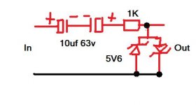
AC couple the input to the amp using a bipolar cap (or use two identical small electros back to back). Probably looking in the 4.7 to 10 uf range at most.
Use a low value (say 1K) resistor in series with the cap.
Add a couple of low voltage zeners (around 2.7 to 5.6 volt depending on amp sensitivity) in inverse parallel across the amp input to clamp any excess voltage swings of either polarity that might appear.
That should protect from practically anything you can apply to the amp input running on the supplies you mention.
- Status
- This old topic is closed. If you want to reopen this topic, contact a moderator using the "Report Post" button.
- Home
- Source & Line
- Analog Line Level
- Protecting my amp during circuit tests