Hi Fotios
Great project, have watched for a while but have now decided to add to my pre-amp.
I only really want vol up / down and maybe the mute function as I will be using the remote from my trusty old Arcam Alpha 7 CD player which has these amp functions on the CD remote")
My question, could I use this Infrared Receiver Buy IR Remote Receiver IR Receiver Module 36kHz Vishay TSOP31236 online from RS for next day delivery. as both variations of the TSOP34836 are on backorder with no delivery date advised, specs seem close enough, can you see any issues?
Cheers
Dagwood
Great project, have watched for a while but have now decided to add to my pre-amp.
I only really want vol up / down and maybe the mute function as I will be using the remote from my trusty old Arcam Alpha 7 CD player which has these amp functions on the CD remote
My question, could I use this Infrared Receiver Buy IR Remote Receiver IR Receiver Module 36kHz Vishay TSOP31236 online from RS for next day delivery. as both variations of the TSOP34836 are on backorder with no delivery date advised, specs seem close enough, can you see any issues?
Cheers
Dagwood
Hi DagwoodHi Fotios
Great project, have watched for a while but have now decided to add to my pre-amp.
I only really want vol up / down and maybe the mute function as I will be using the remote from my trusty old Arcam Alpha 7 CD player which has these amp functions on the CD remote
My question, could I use this Infrared Receiver Buy IR Remote Receiver IR Receiver Module 36kHz Vishay TSOP31236 online from RS for next day delivery. as both variations of the TSOP34836 are on backorder with no delivery date advised, specs seem close enough, can you see any issues?
Cheers
Dagwood
Of course you could use TSOP31236 instead the original 34836, both IR receiver ICs are similar and operate in same 36KHz frequency, viewing angle also is same 90 deg for both, etc. JUST BE CAREFULL REGARDING PINOUTS BECAUSE ARE DIFFERENT! Please study the PDF DATA SHEET of each one IR receiver IC, pinout is refered in the picture at the top of the corresponding "pdf" doc.
Cheers and good luck
I used the TSOP31236
here is what I wrote to Fotios:
Anyway, the RC5 Volume control is really great. I have the Vishay 36 Khz IR Receiver on two meters of shielded cable. The range is amazing. Anywhere in a (70 Sq Meter) room in any direction bouncing off 5 walls works just fine. The circuit also works great with 40 Khz diodes, but not as good as the 36 Khz.
Thank you so much for your precious report!I used the TSOP31236
here is what I wrote to Fotios:
Anyway, the RC5 Volume control is really great. I have the Vishay 36 Khz IR Receiver on two meters of shielded cable. The range is amazing. Anywhere in a (70 Sq Meter) room in any direction bouncing off 5 walls works just fine. The circuit also works great with 40 Khz diodes, but not as good as the 36 Khz.
You are very kind
Fotis
Hi Fotios
Ok, we are up and running....sort of
I will get some photos up shortly
The issue I have is that VR1 only turns in one direction and the mute relay will not work either with the remote or with SW1. I have not connected a relay to the power / standby connection as its not needed for my appliction.
I have used FCv5.HEX
Any thoughts?
Cheers
Hi Dagwood.Hi Fotios
Ok, we are up and running....sort of
I will get some photos up shortly
The issue I have is that VR1 only turns in one direction and the mute relay will not work either with the remote or with SW1. I have not connected a relay to the power / standby connection as its not needed for my appliction.
I have used FCv5.HEX
Any thoughts?
Cheers
First of all check carefully your hardware for any possible mistake. The FCv5.hex file you use (MOT_POT_RC5_FCv5.hex, right?), is configured for PIC16F88 microcontroller. Make sure that you use the same micro. You must use the command "Import File" of the assembler of your programming device, if you use "Open File" will loss the microcontroller configuration bits (osc. frequency etc).
Please let me know.
Hi Fotis
Thanks for the quick reply
I am using PIC18F88 with MOT_POT_RC5_FCv5.hex
I tried to re-load the file ( I'm using PICpgm programmer ) selected "load Hex File" rather than just opening the file but still the same issues.
The only other changes I made was to use different transistors
MPSA06, I used BC546 (now swapped around as pinout is opposit)
MPS2222, I used BC337 (now swapped around as pinout is opposit)
?????
Hi DagHi Fotis
Thanks for the quick reply
I am using PIC18F88 with MOT_POT_RC5_FCv5.hex
I tried to re-load the file ( I'm using PICpgm programmer ) selected "load Hex File" rather than just opening the file but still the same issues.
The only other changes I made was to use different transistors
MPSA06, I used BC546 (now swapped around as pinout is opposit)
MPS2222, I used BC337 (now swapped around as pinout is opposit)
?????
You refer PIC18F88 and i am sure that is a typing error of yours, you mean PIC16F88. OK, your micro is correct. I don't know (i will look on the web for it) your programmer "PICpgm", i just use two programmers the Matrix Multimedia EB006 and the Microchip ICD2. Both ICD2 and PICKIT2 (or the recent PICKIT3) programmers are managed by MPLAB ICD software and for this was my reference "use Import File and not Open File command". But i think "Load File" command of your programmer is the same with "Import File". Well, i will try again to program a PIC16F88 with ICD2 and with the HEX file i have uploaded in Matrix Multimedia forum (NOT this stored in my PC!)and i will confirm you if the file works correctly.
Transistor substitution you did is not problem, your transistors are OK.
Stay tuned.
Fotis
OK DagHi Fotis
Thanks for the quick reply
I am using PIC18F88 with MOT_POT_RC5_FCv5.hex
I tried to re-load the file ( I'm using PICpgm programmer ) selected "load Hex File" rather than just opening the file but still the same issues.
The only other changes I made was to use different transistors
MPSA06, I used BC546 (now swapped around as pinout is opposit)
MPS2222, I used BC337 (now swapped around as pinout is opposit)
?????
Just now i dowmloaded the "MOT_POT_RC5_FCv5.hex" file from Matrix Multimedia forum, i imported the file in MPLAB IDE and i programmed a P16F88 with Microchip "MPLAB ICD2" programmer. Then i installed the P16F88 in the ready "Remotelly Controlled Motorized Volume Pot" test board that i have and i've tried it with 3 different RC5 remote control handsets, the first transmits in RC5 TV address = 0, the second in RC5 Preamplifier 1 = 16 and the third in RC5 Preamplifier 2 = 19. I can confirm you that with any handset the "remote controll mot mot" circuit works just fine without any mistake. The HEX file you downladed is correct. Your problem must be in your hardware, please check it thoroughly. Some times, e.g. a bad solder or a deffective switch could cause problems.
Please let me know.
Fotis
Hmm... have you tried the PICpgm programmer with any other project? I have seen it for first time. I don't knew it. If you are sure that PICpgm is working OK, then continue your search on your PCB, there must be something wrong. Either deffective device or error in mounting. Check 1N4002 diodes if are soldered in correct direction. You could use two LEDs with 470Ω drop down resistors, instead relays to check if STBY and MUTE outputs work OK. Check your hardware again. "LK" marked components actually are simple wire links.Hi Fotis
Thanks for the quick reply
I am using PIC18F88 with MOT_POT_RC5_FCv5.hex
I tried to re-load the file ( I'm using PICpgm programmer ) selected "load Hex File" rather than just opening the file but still the same issues.
The only other changes I made was to use different transistors
MPSA06, I used BC546 (now swapped around as pinout is opposit)
MPS2222, I used BC337 (now swapped around as pinout is opposit)
?????
If you still have problems, you could post me a e-mail in eal@dra.forthnet.gr with your address to post you a ready programmed and tested micro for free. It is not problem, the cost is just of 2 beers
.Fotis
Hi Fotios
I'm away on business for a couple of days but will re-check all parts on Friday.
I have loaded quite a few programs using this programmer with no issues
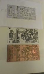
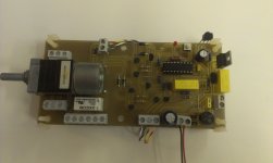
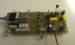
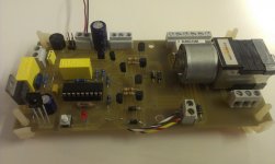
photos attached
I'm away on business for a couple of days but will re-check all parts on Friday.
I have loaded quite a few programs using this programmer with no issues
photos attached
Attachments
Last edited:
Hi DagHi Fotios
I'm away on business for a couple of days but will re-check all parts on Friday.
I have loaded quite a few programs using this programmer with no issues
photos attached
Thanks for pictures, are very informative. I haven't time to check them at the moment, i will do this tomorrow. But from a first view (from those i can see) i think some tracks of "Reset" circuit are missing. I can't see the common connection node of R5 - C6 - R8 - D6. Check it please.
A very important thing i forgot to refer is that: When power is applied to circuit is automatically placed in STBY mode and of course the MUTE output is also activated constantly. You will be able to operate the MUTE function only if you activate the micro by pressing the POWER ON switch on remote control handset. It should be noted that the volume control function is independent in either mode STBY or PWR ON, it works normally in either state.
That's to the present.
Fotis
Hi Fotis
Ok...make that 2 errors! Doh. There is alotto be said for not working on stuff when you are tired
Cheers
Ok...make that 2 errors! Doh. There is alotto be said for not working on stuff when you are tired
Problem, my remote dose not have a power on button....any ideasA very important thing i forgot to refer is that: When power is applied to circuit is automatically placed in STBY mode and of course the MUTE output is also activated constantly. You will be able to operate the MUTE function only if you activate the micro by pressing the POWER ON switch on remote control handset. It should be noted that the volume control function is independent in either mode STBY or PWR ON, it works normally in either state.
Cheers
Attachments
Problem, my remote dose not have a power on button....any ideas
Cheers
Just take another button and use it as a power button. Find out what code the remote is sending when you press the button of choice.
I'm actually in the process of developing a remotely controlled motorized volume pot myself and I have written a little about it here ?music: Remote controlled volume control
Right now the idea is to use an Arduino board and a stepping motor which is controlling an analog volume pot.
Hi DagHi Fotis
Ok...make that 2 errors! Doh. There is alotto be said for not working on stuff when you are tired
Problem, my remote dose not have a power on button....any ideas
Cheers
Are Volume+ and Volume- functions working now? I mean, can be the motor of volume pot rotated CW and CCW using your remote control handset? Please let me know.
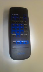
Regarding ARCAM remote handset shown in picture, is for use with CD or DVD player. If it can manage motor rotation in both directions then should be OK. You can make the following test to confirm that can also manage the MUTE relay. Solder a cable in GND (0V) node of PCB. Apply power to remote control board and wait until LED stops to blink. Then, carefully touch the other end of cable at pin 10 of micro, i.e. ground the PwrON/STBY input. Then the MUTE function should be permited.
Try this and if works will proceed in a program code change to use another switch of your handset.
Fotis
Hi Fotis
Yes, Volume + & - are working perfect ( my error)
Arcam remote is for Alpha 7 CD player
Tried shorting pin 10 to ground, still not working??
Maybe I will make another PCB with the errors fixed and remove the Mute relay ( I will leave the function for programming )
Cheers
Yes, Volume + & - are working perfect ( my error)
Arcam remote is for Alpha 7 CD player
Tried shorting pin 10 to ground, still not working??
Maybe I will make another PCB with the errors fixed and remove the Mute relay ( I will leave the function for programming )
Cheers
OK, it shows that your ARCAM remote is compatible with RC5 protocol. Try the following test:Hi Fotis
Yes, Volume + & - are working perfect ( my error)
Arcam remote is for Alpha 7 CD player
Tried shorting pin 10 to ground, still not working??
Maybe I will make another PCB with the errors fixed and remove the Mute relay ( I will leave the function for programming )
Cheers
1) Remove cables from CON6. Get 2 LEDs and screw the cathode (is the short lead of LED, the long is the anode) of each one in the terminals of CON6. Solder one 470R bleed resistor in the other terminal of each LED. Screw the other leads of both resistors at the +5V output of CON6 (is the first from the right side). Apply power to remote control PCB, the LED that is screwed at the left terminal should be lit constantly, that represents the MUTE output. The other LED that is screwed at the middle terminal of CON6 should be stay OFF and represents the PWR On output. Now, try again to ground the pin 10 of micro. The middle (PWR On) LED should be lit now, while the MUTE LED should be turned Off.
If this test works, then your hardware should be OK. Make please this test and let me know. Then i will try a search if the MUTE code is same for both CD and Preamplifier.
Fotis
- Status
- This old topic is closed. If you want to reopen this topic, contact a moderator using the "Report Post" button.
- Home
- Source & Line
- Analog Line Level
- Remotely Controlled Motorized Volume Pot.