... only, because I've such a DIY PS on stock...
Gott sei Dank that you don't have a loaded gun on the stock...
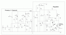
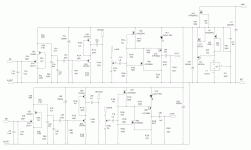
This is the latest version of the SIT preamp I've been trying out, with current source enhancement on the input buffer (and a sex change). Depletion mode MOSFETs are used lavishly throughout as current sources (relatively high current capability with high impedance, minimum parts count).
I tried using a 2SJ74 in the input buffer position, and was rewarded with some high frequency ringing in the step response, which also shows up in the gain-phase measurement. This is perhaps due to the relatively enormous input capacitance of the 2SJ74 (a little bird was whispering in my ear, "use the J175", but I didn't listen).
The attached schematic now shows the J175 (listen to the bird!), and I'll be evaluating that version soon. Both versions (2SJ74 and J175) fared very well in simulation, with about 1/2 the distortion of the original version of this preamp.
The 2.7 pF compensation capacitor shown in the schematic may be replaced with a "gimmick" for optimum response (fast but a trifle overdamped).
Attachments
Last edited:
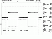
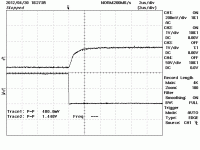
The little bird that occasionally whispers in my ear was right on, as substituting a J175 for the 2SJ74 at the input totally cleaned up the linear square wave response. It's now overdamped with no ringing (and a little slow, if you ask me). Check out the attached waveforms to see what I mean. The trace with the square sides is the input, and the one with the slightly sloped sides is the output. Right now I'm using a 2.7pF NPO disc for compensation, and it looks like a smaller cap would be more optimal. If I can find a regulation cap. I'll use that, otherwise, it's gimmick time...
When I get some spare time, I'll let the HP8903A analyzer take a look. My goal for this project is a circuit that reads at the analyzer residual level for both 1k and 10k input, at input levels that would result in 0.5-1V of output. It's a test of both the circuit and my setup.
When I get some spare time, I'll let the HP8903A analyzer take a look. My goal for this project is a circuit that reads at the analyzer residual level for both 1k and 10k input, at input levels that would result in 0.5-1V of output. It's a test of both the circuit and my setup.
Attachments
Siliconix used the same process for the J174-J177 series (chopper/switch) and the J270-J271 series (linear amp). The J175 and J271 have overlapping IDSS range - the J271 is selected for a narrower range of IDSS. If you have some (J271), it's a possible substitution. If you don't have them, good luck.. The J174-176 series is still available in surface mount and as NOS. I just bought 500 pieces of Fairchild J175 from Electronic Goldmine - they may still have some left. Cheap, too.
One more thing - I selected the J175 for input duty because I have them (always a good reason, if you know how to use what you have), they have a low input capacitance (look it up and compare it to the 2SJ74 - if you are serious about building stuff you should be downloading these data sheets while they're still available!), and a reasonable transconductance (some data sheets will list this, even though it was a part slated for chopper duty).
The J271 was no doubt a selected version of J175 slated for linear amp duty. For a while, it was readily available from Mouser - no more. One other possibility would be the 2N5462, which you can probably still find on Ebay. The input capacitance is where it needs to be, but the transconductance is lower than the J175/J271. Any port in a storm...
The J271 was no doubt a selected version of J175 slated for linear amp duty. For a while, it was readily available from Mouser - no more. One other possibility would be the 2N5462, which you can probably still find on Ebay. The input capacitance is where it needs to be, but the transconductance is lower than the J175/J271. Any port in a storm...
Does this one need any matching please Juma? Is it ok to build as is for a preamp (with a pot in front?Hi Wrench,
here is my take on "turning a (MOS)FET into a SIT/triode". Fair Zin, low Zout, BW(-3dB)=1MHz, rail-to-rail swing (almost), high PSRR, Id about 15mA, sounds wonderfull - what more could a man want ?
Built, tested, measured (except for THD) - here is the schematics:
Hi Wrench,
here is my take on "turning a (MOS)FET into a SIT/triode". Fair Zin, low Zout, BW(-3dB)=1MHz, rail-to-rail swing (almost), high PSRR, Id about 15mA, sounds wonderfull - what more could a man want ?
Built, tested, measured (except for THD) - here is the schematics:
Hm..very interesting
Hm..very interestingWhat is the gain of this circuit?
Already explained in posts #57, 63, 68, 76...
Pics are nice, but reading is still essential
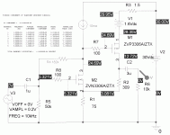
Taking this thread a little further, here's a circuit that uses a "fetfakesit" as an element in a feedback amp for line stage duty. I just finished bread boarding this circuit using a DN2530N3 current source instead of the perfect one used in the simulator, and a GaAsP deep red LED (~1.6 Vf) in the source of the ZVP3306A (simulated via a voltage source and a 1.5 ohm resistor). Voltage levels are very similar to those of the simulation shown. Distortion? Sound? We'll see, as soon as I build up the rest of the board, as it's the stripped carcass of one of my early RIAA/lineamp "preamp-on-a-board" efforts.
Attachments
Last edited:
This is the setup I'll be testing, as soon as I can throw the rest of it together. I'll probably throw things together into a box and change sources by shifting patch cords around, instead of having to do all the baroque wiring needed for the usual rotary source selector switch. At present. all the various elements have the proper quiescent voltages. What remains is to populate the shunt regulator and mount the board in a box with the right connectors.
Attachments
- Status
- This old topic is closed. If you want to reopen this topic, contact a moderator using the "Report Post" button.
- Home
- Source & Line
- Analog Line Level
- If You Don't Have a SIT, Fake It...
