Hi everybody!
Is there any design that implements a full 24db/oct crossover in three opamps instead of four? Is it even possible?
The reason I'm searching for something like this is I want to squeeze the crossover plus an artificial ground into one quad opamp...
My first thought was to simply build a linkwitz sallen key low pass and sending the output with the signal input to a differential amplifier but of course that doesnt work (I think it is because of the phase shift caused by the low pass filter?)
hope you can help me!
Does it have to be 4'th order then? I expect the capacitors will be more expensive than the opamps, and take up more space.I'm not searching for good sound quality. it must be small and cheap...
If you want to do everything with 4 opamps you could easily do a good 2'nd order crossover with one opamp each for: input buffer, low pass, high pass, and virtual earth.
Because I doubt you will able to find a great quad op amp but as your not going for the best sound quality then I guess your okay.
LME49740 is a great quad. It's bi-polar input though, maybe jfet would be better (opa4134?).
You can do any order with just 2 opamps. Silly enough, you can do without opamps too, as long as your source output impedance and amplifier's input impedance are known and stay constant.
Make passive networks as you do with loudspeaker passive crossovers.")
You can live without inductors - just use RC filter, and calculate the following stage as if it have input impedance of R+Rsource.
Gonna be messy.
3 opamps:
1. Input buffer
2. HP buffer
3. LP buffer
+ passive network in between.
You can go with 3rd order per single opamp in Sallen-Key way - 3rd order Sallen-Key Low-pass Filter Design Tool
Make passive networks as you do with loudspeaker passive crossovers.
You can live without inductors - just use RC filter, and calculate the following stage as if it have input impedance of R+Rsource.
Gonna be messy.
3 opamps:
1. Input buffer
2. HP buffer
3. LP buffer
+ passive network in between.
You can go with 3rd order per single opamp in Sallen-Key way - 3rd order Sallen-Key Low-pass Filter Design Tool
Hi,
If its driving diy amplifiers you can move the last low pass section to in
the treble amplifiers feedback loop. Can't do that with the bass unless you
slug the bass amplifier for unity gain stability. You can though build a low
frequency lowpass around the bass amplifier as boost / subsonic filter.
rgds, sreten.
Could you explain how this is done?You can live without inductors - just use RC filter, and calculate the following stage as if it have input impedance of R+Rsource.
Gonna be messy.
S3,
I don't need the answers I need the method to determine the answers.
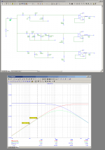
Can you talk me through the 2pole High Pass shown?
C7, C8, R11, R17, R18.
How do you correct the component values for the non zero source impedance and the non infinity load impedance?
How do you arrange for the Q to come out at the desired value?
I don't need the answers I need the method to determine the answers.
Can you talk me through the 2pole High Pass shown?
C7, C8, R11, R17, R18.
How do you correct the component values for the non zero source impedance and the non infinity load impedance?
How do you arrange for the Q to come out at the desired value?
AndrewT, I've spent 2 evenings on the matter
First time i've managed to get the calculations work, but when i've dialed-in the 2nd stage, i always got -6db at filter's Fo. Filter's Q didn't vary much, something between 0.5 and 0.707, maybe 1.
Second time i calculated the transfer function for the circuit, simplified it to the
(s+1)/(s^2+s+1)
form, and then again i've got stuck
I tried to solve the equation for H=2, but got some unrealistic numbers.
I think it's the right time to google for help
- Status
- This old topic is closed. If you want to reopen this topic, contact a moderator using the "Report Post" button.
- Home
- Source & Line
- Analog Line Level
- Three opamp 24db/oct crossover?