")
Both versions are on breadboard and no fancy parts.
The B1 is the version published in the First watt site .
There is no caps on the Diamond buffer board but a 2 uf cap in B1 as published.
I use it after the lightspeed clone and before the amp. The amp is a the Death of Zen variant .
My dac is discrete monica from diyparadise and Buffalo 2 from twisted pear.
cheers
kp93300
I am trying to make things as simple as possible in my setup these days. And while thinking about b-boards and vpsps/phonoclone and some inspiration by Martin (http://www.diyaudio.com/forums/analogue-source/133191-phonoclone-3-a-72.html#post2948701), I noticed that according to the recomendations on post 13 (http://www.diyaudio.com/forums/analog-line-level/205522-rjm-audio-b-board-project-2.html#post2937832) we are basically creating something like the recommendation on post 23 (http://www.diyaudio.com/forums/analog-line-level/205522-rjm-audio-b-board-project-3.html#post3007283) without the potentiometer, the coupling cap after the buffer and a 33K resistor instead of 100K.
Would it be safe to add an attenuator and a source selector to the circuit of post 13 right after the buffer and before C3 and R7 to effectively create a full unity gain preamp with built-in phono? Does it matter (for DC spikes or whatever) if the coupling cap is after the buffer?
Thanks again
Would it be safe to add an attenuator and a source selector to the circuit of post 13 right after the buffer and before C3 and R7 to effectively create a full unity gain preamp with built-in phono? Does it matter (for DC spikes or whatever) if the coupling cap is after the buffer?
Thanks again
As easy as flipping Q1 with Q2?
err. No.
Regarding interfacing the B-board with the Phonoclone.
While coupling capacitors might be more audible than other individual components, most preamp designs have several for good reason: they are extremely useful.
Despite what I wrote in previous posts, the best way to do what you are thinking of (phonoclone + B-board full featured preamp) is to keep the phonoclone stock, and route the output to a selector switch which also sources from a set of RCA line inputs. Then the principle signal is run though the mute, stereo/mono, balance, and volume controls, followed by a coupling capacitor, followed by the input resistor and the B-board, then to the output RCA jacks (with A/B switch if you want). You can also add a tape buffer (another set of B-boards) and/or a headphone amp.
It's not so much complicated as it is painstaking, which is why I think such projects are relatively rare here on diyaudio.
If you need help I can send you some schematics of commercial preamps that show how to configure all the controls.
Attachments
Hmm
I would expect a cheapish DC coupling cap to significantly affect the sound
The cap that i use is WIMA MKS 2.2 Uf
While coupling capacitors might be more audible than other individual components, most preamp designs have several for good reason: they are extremely useful.
Thanks a lot for the answer Richard
Do you mind elaborating a bit? The reason I thought of the above was simplicity.
I really do not need all those switches. Only a 2 way source selector and a volume pot, both of which I am thinking of implementing with LDRs, so no clicking or scratching from them.
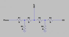
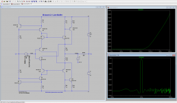
Something like that
When phono is on, R1 and R5 act as the attenuator, while R2 is ~30R.
At the same time R3 and R4 are ~50M while R6 is ~30R.
When CD is on, R4 and R6 act as the attenuator, while R3 is ~30R.
At the same timeR1 and R2 are ~50M while R5 is ~30R.
And on mute, all series resistors are ~50M, and Shunt ones ~30R.
Sorry for the longish post. I just really value your opinion
Attachments
B-board 3.0
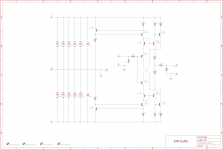
In line with the last revision, the bboard will (hopefully) be updated to feature the improvements first developed for the Sapphire headphone amplifier.
Briefly, the changes pretty much copy the new Sapphire directly:
* active constant current sources replacing the emitter resistors
* Szilkai output
* BC337/BC327 transistors and 1/4W resistors
The parallel output transistors will be removed and the bias currents scaled down (optionally, they can be increased if you need to drive very low impedance loads). I'll include an input resistor this time... it makes it simpler.
My main concern is the layout and whether I can make the same compact board layout as before. One option is to remove the Z-reg section and feed the board from a regulated supply such as the V+/V- pads on the phonoclone board or an X-reg board.
Attachments
Well that's embarrassing.
Coming back to this thread I find my latest version has a smaller revision number than the last version I posted here. Oops.
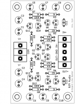
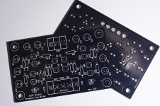
This is revision "2.1f1". It's a derivative of 3.0 above, I guess, actually simplified and downscaled a little with no loss in performance. The boards are just the buffer circuit with no regulation. You can power it however you like, with split supplies from 5 to 18 V. Current draw is ~<10 mA.
Coming back to this thread I find my latest version has a smaller revision number than the last version I posted here. Oops.
This is revision "2.1f1". It's a derivative of 3.0 above, I guess, actually simplified and downscaled a little with no loss in performance. The boards are just the buffer circuit with no regulation. You can power it however you like, with split supplies from 5 to 18 V. Current draw is ~<10 mA.
Attachments
- Status
- This old topic is closed. If you want to reopen this topic, contact a moderator using the "Report Post" button.
- Home
- Source & Line
- Analog Line Level
- RJM Audio B-Board Project