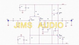
Does anyone have any suggestions on improving this discrete op amp circuit? I know it's old and probably considered primitive today, but I thought I'd ask anyway. I don't have the component values yet, sorry. It's basically a differential pair driving a single ended output wherein the output transistor has a constant current load. One improvement I can see is to put a small capacitor in parallel with R6 to provide a high frequency pole. I probably won't run it at +/- 32 volts though.
I was going to use it only as a buffer in a preamp.
Yeah, I know, Jim's Audio. If you hate them, please keep it to yourself.
I was going to use it only as a buffer in a preamp.
Yeah, I know, Jim's Audio. If you hate them, please keep it to yourself.
Attachments
Hi,
Not improve your eschematic, but you can find in this web page some other discrete opamps. This are also easy and cheap:
VU-Meter
Happy days
Thanks. very interesting.
I think maybe I don't need to bypass R6 because of C4 and C6. I think C4 is called a "Miller" capacitor, but I could be wrong.
I don´t like the output via transistor collector, too high impedance point to put a long wire, and the CCS, mmmhh, I would prefeer emitter follower instead, and if possible, bootstrapped to increased linearity and gain.
Yeah, it's not ideal, I agree. I'd prefer a push pull arrangement on the output, but I already bought the boards.
The preamp I have in mind would have to drive two outputs at the same time. One to a balanced output via a transformer, the other to a single ended output. I was going to use this as a buffer between the preamp and the single ended output. I don't have the capability to make my own circuit boards or design my own circuit.
When I first glanced at it before buying, I thought it was an emitter follower but after studying it some more I realize I was incorrect. Oh well, what ever.
In my opinion, high impedance to drive a transformer, you will have a lots of problems like hum, resonances, high end cut, etc. I would prefer some push pull low Z driver.
This isn't driving a transformer. Sorry for the misunderstanding. I have a good low impedance circuit for that. This drives the subwoofer single ended outputs only. So, I don't need high bandwidth. It's just going to be connected to a pair of RCA connectors.
C6 is a Miller capacitor. C4 appears to be injecting noise from the negative rail, maybe as some sort of cancellation technique? Very crude circuit, high distortion, high output impedance; you might be better off using a 741!
Well, not to throw stones, but the Pass B1 buffer isn't exactly complex and elegant.
I suppose I can delete the C4 capacitor. Offhand I'd say it shunts HF to -32V rail, but what do I know. It's 5pF from what I can gather by looking at the board.
... Sorry for the misunderstanding. .
Don´t worry.
Here's some discussion of this kind of circuit, though I'm sure most here already know all about it:
Discrete Operational Amplifier
An even more simple circuit is here:
http://sound.westhost.com/project37a.htm
The subwoofer plate amp I'm using has an input impedance of 20kohms. This should be able to drive that no problem, shouldn't it? The cable may be up to 2 meters long.
Discrete Operational Amplifier
An even more simple circuit is here:
http://sound.westhost.com/project37a.htm
The subwoofer plate amp I'm using has an input impedance of 20kohms. This should be able to drive that no problem, shouldn't it? The cable may be up to 2 meters long.
Last edited:
If all you want is a buffer then perhaps an emitter follower or FET source follower with constant current loading might be worth considering. I think it would outperform the above (post #1) on sonics everytime.
Yeah, maybe I should have bought the Pass B1 buffer instead. We'll see. Let me look around.
Jim's Audio has the B1 buffer board. No problem. got it.
Last edited:
I don't think you realise what a poor circuit it is. At the very least it needs a follower on the output. Why complicate things? Either use a decent op-amp, or a simple follower - a complementary pair would do the job.dirkwright said:This should be able to drive that no problem, shouldn't it?
I don't think you realise what a poor circuit it is. At the very least it needs a follower on the output. Why complicate things? Either use a decent op-amp, or a simple follower - a complementary pair would do the job.
Well, like I said, I don't have the ability to design my own circuit nor make printed circuit boards. I'm not interested in acquiring the software and equipment to do that either. According to the web sites I've provided, it isn't as bad as you say.
I've bought the B1 buffer, but I think I may want some gain in this channel so I may use this op amp to drive the buffer. I don't know yet. I'm still planning.
The standard of the pro audio industry is the Jensen 990 discrete op amp.
http://www.johnhardyco.com/pdf/990.pdf
http://www.johnhardyco.com/pdf/990.pdf
The standard of the pro audio industry is the Jensen 990 discrete op amp.
http://www.johnhardyco.com/pdf/990.pdf
yeah. Looks really nice. I'm sure it's $$$.
- Status
- This old topic is closed. If you want to reopen this topic, contact a moderator using the "Report Post" button.
- Home
- Source & Line
- Analog Line Level
- discrete op amp