Now that the schematic is just about correct, start investigating what voltages exist around the circuit.
Start investigating what currents are flowing around the circuit.
Start understanding why the circuit works.
Remember I was trying to get you to investigate the voltages around the output stage loop.
Do that now for this latest schematic.
You will find an anomaly. The red LED voltages needs to be VERY low to get your circuit to bias properly.
I've been doing that all along, from the beginning. I just never thought to mention it to you. It's a normal part of designing the circuit.
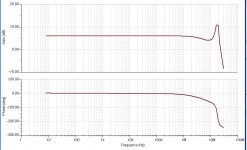
Dang Darlingtons! This often happens when I add them to a circuit. The resonance at about 19MHz is a pain in the neck. What suggestions can anyone make to damp this resonance (besides the Miller and feedback capacitors)? I suppose I could just ditch the darlingtons all together.
Attachments
If you had been doing that, then you would have spotted the LED anomaly
Look, I'm trying to be polite to you, but you are really pushing me.
"But first it should be noted that LEDs are rated with a nominal forward voltage drop. If an LED is connect up such that it is emitting light, a multimeter can be used to measure a voltage drop across the LED. This voltage drop usually varies from 1.5V up to 5V, depending on the power output of the LED, and also the color. Low power LEDs tend to have low voltage drops, and high power LEDS have the higher voltage drops. Likewise blue or white LEDs tend have higher voltage drops, than red LEDs."
1.47V forward voltage is not outside the realm of normal for LEDs.
2.94V to bias on a pair of Darlingtons does not sound right.
2.4V to 2.5V is more the ballpark your Darlingtons should be near.
That would require 1.2Vf to 1.25Vf for the red LEDs.
Red LEDS normally have Vf from 1.5Vf to 1.9Vf.
You should be able to see that just by looking at the schematic.
If you can't "see" that, then ask the sim to tell you the voltages and currents around that output loop.
OK, if you say so.1.47V forward voltage is not outside the realm of normal for LEDs.
Have you looked at the datasheet for that one?...it's just a normal red LED. I've selected this one:
HLMPD155A Everlight Standard LED - Through Hole
Edit: Oops, I see I already showed you that graph last month. Sorry for the repeat.
Attachments
Last edited:
Get rid of the 220pF capacitor. Increase the 22pF capacitor if necessary. Maybe add base stopper resistors for the output devices.The resonance at about 19MHz is a pain in the neck. What suggestions can anyone make to damp this resonance
That's the smart option if this is going to be a preamp. For a power amp, you won't have enough current gain without Darlingtons.I suppose I could just ditch the darlingtons all together.
Also the temperature coefficient for the forward voltage of red LEDs is a reasonable match to one base-emitter forward voltage, not two. So you will still have a tendency to a large increase in output devices' quiescent current with temperature, both ambient and signal-induced. You'll be closer to stability with two standard (~1N4148) diodes in series in place of each LED.
Remember that where almost all Spice falls down terribly is accounting for temperature. With some sand-state devices this isn't as much of a fatal flaw as with others, but bipolars are very susceptible to fatal errors. That is why the counsel of emitter resistors is well-founded.
Brad
Remember that where almost all Spice falls down terribly is accounting for temperature. With some sand-state devices this isn't as much of a fatal flaw as with others, but bipolars are very susceptible to fatal errors. That is why the counsel of emitter resistors is well-founded.
Brad
Also the temperature coefficient for the forward voltage of red LEDs is a reasonable match to one base-emitter forward voltage, not two. So you will still have a tendency to a large increase in output devices' quiescent current with temperature, both ambient and signal-induced. You'll be closer to stability with two standard (~1N4148) diodes in series in place of each LED.
Remember that where almost all Spice falls down terribly is accounting for temperature. With some sand-state devices this isn't as much of a fatal flaw as with others, but bipolars are very susceptible to fatal errors. That is why the counsel of emitter resistors is well-founded.
Brad
Tina has a temperature drift for DC analysis available. I tried it out. The voltage at the junction of the two final emitter resistors goes down with temperature, from about 1.7V to about 1.6V @ 100deg C. not sure where you want the DC drift with temperature measured.
Tina has a temperature drift for DC analysis available. I tried it out. The voltage at the junction of the two final emitter resistors goes down with temperature, from about 1.7V to about 1.6V @ 100deg C. not sure where you want the DC drift with temperature measured.
Tina and all other simulators that I know of that have a temperature function account for ambient changes only. That's a start, but the more pernicious effects are due to signal-induced changes and orders of magnitude more difficult to model. There are many thermal time constants and thermal resistances for example, the chip, the chip to package, the package to ambient or heat dissipator...
But if your emitter resistors are large enough you can shrug most of this off.
Brad
The voltage between that junction and what? ground? That's just the DC offset.Tina has a temperature drift for DC analysis available. I tried it out. The voltage at the junction of the two final emitter resistors goes down with temperature, from about 1.7V to about 1.6V @ 100deg C.
The voltage between the emitters of the output transistors, or just measure the collector current of one of them. With emitter resistors it should be OK. Without them, there would be a problem, and it would be much worse if the transistors are heated up and the LEDs/diodes stay cool (as is likely in real life)....not sure where you want the DC drift with temperature measured.
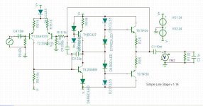
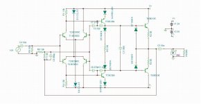
I think this one is pretty good. I gave up on those Darlingtons. The RF resonance issue is just too hard to fix. This one rolls off nice above 1MHz. Distortion into 32 ohms is something like 0.00015% at full output for headphones. Headroom is huge, with 0.001% distortion at over 8 volts rms output, 1kHz. Gain is 6dB out to 1MHz. This is in sim land though...
I may have a use for another headphone amplifier, so this one may get built.
I still don't completely understand how a diamond buffer works, but I'm glad it does work well.
I may have a use for another headphone amplifier, so this one may get built.
I still don't completely understand how a diamond buffer works, but I'm glad it does work well.
Attachments
This are a comercial, and well tested, design.
Happy days
That looks something like the JE990.
You have to realize that I am not designing this from scratch. I'm working from some circuit boards I got from Jim's Audio, as described at the beginning of this thread.
If I was building from scratch, I'd do something different.
It would be fun to try to "out gun" all the guys who make DOA's for the professional audio industry. There are many small manufacturers of these little 1" square boards that work in place of the famous JE990. Of course, these pro audio guys often go for some kind of "sound" from their gear. One manufacturer has specifically tailored the distortion spectrum for one his DOA's to match a vintage one. Why???

You might as well make some using Nuvistor tubes...
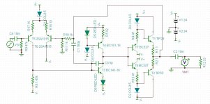
Well, this does perform very well. Something like 3.5x10^-5% distortion @ 1kHz into 600ohms. There's a nasty spike at 10MHz or so. I tried to tame it but don't really have an idea. It would most likely fit on a 1" square PCB. I don't understand the function of the 100nF capacitor, nor the 150ohm resistor between the two diodes. Also, I don't know the function of the last 2 diodes connected to the output transistors, but I was able to figure out that the input is just two LTP's of opposite polarity. I think this is to reduce even order distortion?
I continue to mess around with this one. I removed some of the capacitors and reduced the Miller capacitor and the distortion is even lower but the resonance at 40MHz or so is still there.
I continue to mess around with this one. I removed some of the capacitors and reduced the Miller capacitor and the distortion is even lower but the resonance at 40MHz or so is still there.
Attachments
Last edited:
Raul_77's submission appears to be one of the Bryston bipolar discrete op amp circuits. Bryston build these with cheap ferrous metal film resistors, input and output ferrous leaded electrolytic coupling capacitors for each gain stage or buffer ( 2 to 6 caps a channel in total), somewhat generic bipolar semiconductors (now the low current devices are custom labelled for them to reduce cloning) and a single pair of fixed three terminal regulators for the entire preamp or crossover it is used in. They meet a price point marketing discrete topology, but lack the design and build quality to be high end.
I find the Bryston sound grainy, unresolving, and compressed compared to well built versions of Pass, Curl, and Borbely's type of fet and jfet circuits which sell for (and cost to build) considerably more. Well built means Jung or shunt regulators for each stage and channel, non magnetic and/or bulk foil resistors, Blackgate or Elna or other non ferrous caps, gain matched devices, and dc servos where possible.
The additional effort of building a discrete op amp is rewarded best when the input devices are select matched low noise / low capacitance fet and Jfet types and outputs are highly biased TO 220 fets fed with good local regulators and made with premium passive components.
Last edited:
Yes, are from Bryston, as example are used in the B100 integrated:
Bryston Limited: Technical Documents
http://bryston.com/PDF/Schematics/B100_SCHEMATICS.pdf
Happy days
Bryston Limited: Technical Documents
http://bryston.com/PDF/Schematics/B100_SCHEMATICS.pdf
Happy days
isolation transformer better at the receiving end?
I well realize this is an old thread, but this message triggers an interesting question.
At least I read it at such: putting an isolation transformer better at the receiving end (@ destination) than at the sending end of a cable (@ source).
I've dug up some Whitlock-articles again, should ponder a bit more about this myself as well. Application here is to isolate grounds for an in essence unbalanced to unbalanced connection (LowZ source into a HighZ destination)
Thanks
I ask again:
A balanced to unbalanced input transformer inside the yet to be built power amp will perform far better than an output transformer at the Source.
Have you read any of Whitlock?
Do you really need a balanced impedance connection?
I well realize this is an old thread, but this message triggers an interesting question.
At least I read it at such: putting an isolation transformer better at the receiving end (@ destination) than at the sending end of a cable (@ source).
I've dug up some Whitlock-articles again, should ponder a bit more about this myself as well. Application here is to isolate grounds for an in essence unbalanced to unbalanced connection (LowZ source into a HighZ destination)
Thanks
- Status
- This old topic is closed. If you want to reopen this topic, contact a moderator using the "Report Post" button.
- Home
- Source & Line
- Analog Line Level
- discrete op amp