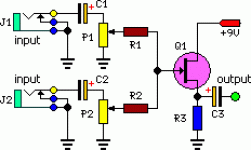
Here's the link:
http://www.extremecircuits.net/2009/07/stereo-to-mono-converter-based-on-fet.htm
Here's my problem: I'm trying to find a 0.1uF 25v capacitor, but all I can find is 50v ones. Is it ok for me to use a 0.1uF 50v capacitor instead of the 25v one?
I read somewhere on the net that it is best to use the capacitor that is closest to the amount of power coming in (+9v).
I did find some 25v capacitors, but they were Surface mount. I really don't have experience with surface mount capacitors and I am not even comfortable trying to solder them. I'd rather the capacitors that have legs on them.
Any help?
Without knowing the purpose of this circuit it's hard to comment much, but I'd have to be really armtwisted to use any input capacitors at all (or even any active circuitry at all, as nigelwright7557 says). If they were necessary because of possible DC voltages appearing at the inputs, I'd want much higher voltage non-polarized caps and some kind of overvoltage clamps, maybe zeners. What kind of guitars is this to be used for?
All good fortune,
Chris
All good fortune,
Chris
I wasn't actually planning on using it for guitars..... I just needed a stereo to mono circuit to convert a stereo line to mono.
The reason I picked this specific schematic is because it is possible to add as much "channels" as you want.
If that were not the case, I would have simply just wired both audio signals to create a mono signal and call it a day.
The reason I picked this specific schematic is because it is possible to add as much "channels" as you want.
If that were not the case, I would have simply just wired both audio signals to create a mono signal and call it a day.
0.1uF sounds a bit low depending on the value of the pots. The effect of the cap is to roll the bass off because it forms a high pass filter.
Have a read at this,
High-pass filter - Wikipedia, the free encyclopedia
Same goes for C3, as the load impedance you hang on the end of this circuit also forms a filter.
I would use small 4.7 uF electroylitics all round I think (watch the polarity), and it would be good practice to add a resistor to ground across each input and also across the output to "charge" the caps at switch on.
- Status
- This old topic is closed. If you want to reopen this topic, contact a moderator using the "Report Post" button.
- Home
- Source & Line
- Analog Line Level
- Stereo to Mono Circuit: need help with capacitor
