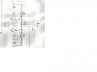
A line stage I have has a folded cascode output buffer. There's a 100ohm resistor on the output, as shown in the box. I was wondering if there would be an advantage to replacing it with a small inductor. This is to improve RFI rejection, at least. If this would be a good idea, then how do I pick a good inductance value? Do I go by self resonant frequency, or what? The output could be driving 300ohm headphones or an amp with 10Kohm input impedances.
Attachments
I would not be keen on using an inductor alone.
I suggest your split the 100r into two 51r in series.
Bypass one of the 51r with a 10uH coil.
Check stability after this mod.
You may have to look at adding a Zobel to complete the Thiele Network.
I suggest your split the 100r into two 51r in series.
Bypass one of the 51r with a 10uH coil.
Check stability after this mod.
You may have to look at adding a Zobel to complete the Thiele Network.
I would not be keen on using an inductor alone.
I suggest your split the 100r into two 51r in series.
Bypass one of the 51r with a 10uH coil.
Check stability after this mod.
You may have to look at adding a Zobel to complete the Thiele Network.
Would you happen to know the function of this particular resistor? Is it protection against shorts on the output or what?
It is probably to stop the follower from oscillating. Any follower with a capacitive load can become a negative resistance oscillator, due to phase shifts within the devices. An inductor won't help, as the aim is to overcome negative resistance.
It is probably to stop the follower from oscillating. Any follower with a capacitive load can become a negative resistance oscillator, due to phase shifts within the devices. An inductor won't help, as the aim is to overcome negative resistance.
OK, thanks. I'll leave it there then. I'll have to read up on RFI protection for line level gear.
The resistor may prevent the circuit from causing RFI to other radio users in the vicinity.
Do people even put zobel or other networks on the outputs of line level gear? I've never seen any, though that's not saying much.
the circuit is not a folded cascode - it is basically a complementary double emitter follower - often called a "diamond buffer"
the input Q collectors are bootstrapped by being connected to the opposite out Q emitters - but the collector current isn't used further - so no cascode - only bootstrap
the 100 Ohm R is a good compromise for adequately low line out output Z, load C isolation and some RF decoupling, possible short circuit limiting (check power rating)
with capacitive emitter load an emitter follower shows negative input R and may oscillate - either series R or L can decouple the emitter from capacitive cable load and prevent this negative resistance at the base of the Q
the 47 R may be intended as "base stoppers" and can help with the negative resistance input problem - to oscillate the negative resistance needs a complex impedance input driving the Q base
for headphone drive you may want lower output Z, then the parallel inductor or lossy ferrite bead may be useful in giving low Z at audio while increasing thru low RF to a resistive region at mid/hi RF frequencies - you need to select material, core size for the right resistive value over the right RF frequency range, and pay attention to DC bias saturation spec - audio current being "DC" for the RF ferrite performance
the circuit is not a folded cascode - it is basically a complementary double emitter follower - often called a "diamond buffer"
the input Q collectors are bootstrapped by being connected to the opposite out Q emitters - but the collector current isn't used further - so no cascode - only bootstrap
the 100 Ohm R is a good compromise for adequately low line out output Z, load C isolation and some RF decoupling, possible short circuit limiting (check power rating)
with capacitive emitter load an emitter follower shows negative input R and may oscillate - either series R or L can decouple the emitter from capacitive cable load and prevent this negative resistance at the base of the Q
the 47 R may be intended as "base stoppers" and can help with the negative resistance input problem - to oscillate the negative resistance needs a complex impedance input driving the Q base
for headphone drive you may want lower output Z, then the parallel inductor or lossy ferrite bead may be useful in giving low Z at audio while increasing thru low RF to a resistive region at mid/hi RF frequencies - you need to select material, core size for the right resistive value over the right RF frequency range, and pay attention to DC bias saturation spec - audio current being "DC" for the RF ferrite performance
Yeah, thanks for that. I don't know where I got the idea that this was a folded cascode.😱 No wonder it didn't match up with all the folded cascodes I looked at on Google. 😱
OK, I'll try to learn something about using ferrite beads. Thanks for the suggestion. Maybe I shouldn't use this to drive headphones anyway.
Thanks very much for your time and helpful suggestions.
- Status
- Not open for further replies.
- Home
- Source & Line
- Analog Line Level
- output inductor?