James, your post reads like a classified add, but I agree it would be simpler and cheaper (in the long run) to buy one rather than build a copy.
The electrolytics in a 40 year old component are of questionable status, despite your checks. Let's face it they must be on their way out by now. That's not what's holding me back though; it's just a matter of purpose - I'm more interested in the circuit than the preamplifier per se.
When you said it, I reread my post and it does seem a bit like classified. It's just that my enthusiasm got carried about C-21 but trust me, I got nothing for sale and C-21 is going to stay with me for a very long time. I like to keep such samples as a gauge for my audio journey.
Recapping the C-21 is real simple so I may just do that one day soon.
Since this is a DIY section, I am all in for building a C-21 clone but I got curious why you want to build this particular pre thus the question.
Hi,
As you are in Japan, last year or so MJ did a review on a Preamp by Phasetech (their solid state offering).
It uses a very interesting open loop line stage with what you may call a Fet-Diamond frontend, notable for it's use of the still available and easy to get 2SK246 and 2SJ103. It would be easy to arrange this circuit run both with and without looped feedback.
Kimura San's headphone amplifier incidentally may also be used without any feedback with minor re-adjustment.
Past that, no need to teach chinese (mainland or otherwise) KopyMao's new tricks...
Ciao T
Probably this one, or this slightly cheaper variant.
Nice find.
re the 47 labs amp, yes I see, I think: the feedback resistor could be grounded to cut the feedback loop back to the previous stage and the whole thing should still basically hang together.
Nice find.
re the 47 labs amp, yes I see, I think: the feedback resistor could be grounded to cut the feedback loop back to the previous stage and the whole thing should still basically hang together.
Attachments
I am all in for building a C-21 clone but I got curious why you want to build this particular pre thus the question.
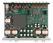
I got the impression from looking at the schematic that the designer had considerable skill and the circuit was carefully optimized for sound quality. PRR disagrees, but that was anyway my feeling after looking through a dozen or so similar documents. The other option was the Classe DR-4, but I considered that a bit too complicated.
Hi,
We try. Given that what most people do bores me to death due to a total lack of innovation I have to cast the net wide for things that are interresting.
Essentially, the resistor to ground (part of the FB Loop) sets the transconductance of the circuit (it is voltage in - current out).
A second resistor then can set the gain because with a known transconductance we can set the gain simply with a resistor from the output to ground.
I would personally replace the diamond transistor with a pair of J-Fet's (1pc N-Channel, 1pc P-Channel), the mentioned 2SK246 and 2SJ203 would be a good choice.
The beauty is that while these circuits CAN use looped feedback, they do not have to and they can even be made switchable between the two alternatives if desired.
For line outputs a direct output is okay if the design is sound (pun intended), for 'can's I would add a nice open loop Fet-Diamond buffer...
Ciao T
We try. Given that what most people do bores me to death due to a total lack of innovation I have to cast the net wide for things that are interresting.
re the 47 labs amp, yes I see, I think: the feedback resistor could be grounded to cut the feedback loop back to the previous stage and the whole thing should still basically hang together.
Essentially, the resistor to ground (part of the FB Loop) sets the transconductance of the circuit (it is voltage in - current out).
A second resistor then can set the gain because with a known transconductance we can set the gain simply with a resistor from the output to ground.
I would personally replace the diamond transistor with a pair of J-Fet's (1pc N-Channel, 1pc P-Channel), the mentioned 2SK246 and 2SJ203 would be a good choice.
The beauty is that while these circuits CAN use looped feedback, they do not have to and they can even be made switchable between the two alternatives if desired.
For line outputs a direct output is okay if the design is sound (pun intended), for 'can's I would add a nice open loop Fet-Diamond buffer...
Ciao T
Hi,
Looking through a wide range of circuits I find the C-21 very generic in terms of circuit, with much attention paid to and money spend on the passive components (not necessarily a bad choice TBH), but the gain circuit can really be improved upon, a lot actually...
In my view the design of the Phase Tech CA3 instead is one that evidences considerable skill in circuit design and optimisation out of 10 I'd give it 9, with the pioneer scoring maybe 3...
Ciao T
I got the impression from looking at the schematic that the designer had considerable skill and the circuit was carefully optimized for sound quality. PRR disagrees, but that was anyway my feeling after looking through a dozen or so similar documents. The other option was the Classe DR-4, but I considered that a bit too complicated.
Looking through a wide range of circuits I find the C-21 very generic in terms of circuit, with much attention paid to and money spend on the passive components (not necessarily a bad choice TBH), but the gain circuit can really be improved upon, a lot actually...
In my view the design of the Phase Tech CA3 instead is one that evidences considerable skill in circuit design and optimisation out of 10 I'd give it 9, with the pioneer scoring maybe 3...
Ciao T
Hey up, back after New Year...
Agree that the C-21 circuit is "generic". I just thought it was a well-thought-out implementation.
So turning to the 2SJ103/2SK246 jfets, I suppose with access to complementary pairs any bipolar-based preamplifier circuit can be re-jigged to use jfets, including the LH002 "diamond buffer", variations thereof, or the current-feedback-amplifier "diamond buffer + current mirror" circuit of 47 labs.
Since Phase Tech don't give too much info on their web page and I don't have easy access to the MJ article, I'm left in the dark about the circuit. Looks from the photo to have about a dozen TO-92 transistors per channel, and the blurb touts it as a "full symmetrical non-feedback circuit" which sounds rather like the 0247 circuit with the feedback connection cut... though "full symmetrical" suggests a doubling somewhere dealing with balanced input signals.
This might possibly be related.
The search continues.
Other than being more careful to match components and remember that voltage offsets will be less stable, is there any "gochas" in using jfets over bipolars that I'm missing?
Hi,
Richard. You are in Kyoto and you cannot get MJ Backissues? How do you think us kawaii gaijin who rarely visit Japan are doing!?
I get them when I'm in Hong Kong... Some of Shops there usually have a years worth or two in stock for crazy people like me... I can see if I scan the schematic when I have time, sadly my scanner is sheet feed, not flatbad, so it will take time.
The Symmetric Circuit in this case is meant rail symmetric.
It uses the K246/J103, then a enhanced wilson current mirror (IIRC) with gain into a load resistor and then a buffer. It's actually very similar to the circuit you find in Ayre gear as well, but CH has squirrelled away massive numbers of K170/J74 (I have more modest numbers, but already pair-matched) so he uses them.
No, by using BJT's you get some extra gotch's though...
My favourite J-Fet mod of all times is to replace the input transistor of Naim Line Stages with a BF244 (or 245, whichever has the right pinout) and then remove anything between J-Fet and Pot. Quite a revelation actually...
Ciao T
Since Phase Tech don't give too much info on their web page and I don't have easy access to the MJ article, I'm left in the dark about the circuit. Looks from the photo to have about a dozen TO-92 transistors per channel, and the blurb touts it as a "full symmetrical non-feedback circuit" which sounds rather like the 0247 circuit with the feedback connection cut... though "full symmetrical" suggests a doubling somewhere dealing with balanced input signals.
Richard. You are in Kyoto and you cannot get MJ Backissues? How do you think us kawaii gaijin who rarely visit Japan are doing!?
I get them when I'm in Hong Kong... Some of Shops there usually have a years worth or two in stock for crazy people like me... I can see if I scan the schematic when I have time, sadly my scanner is sheet feed, not flatbad, so it will take time.
The Symmetric Circuit in this case is meant rail symmetric.
It uses the K246/J103, then a enhanced wilson current mirror (IIRC) with gain into a load resistor and then a buffer. It's actually very similar to the circuit you find in Ayre gear as well, but CH has squirrelled away massive numbers of K170/J74 (I have more modest numbers, but already pair-matched) so he uses them.
Other than being more careful to match components and remember that voltage offsets will be less stable, is there any "gochas" in using jfets over bipolars that I'm missing?
No, by using BJT's you get some extra gotch's though...
My favourite J-Fet mod of all times is to replace the input transistor of Naim Line Stages with a BF244 (or 245, whichever has the right pinout) and then remove anything between J-Fet and Pot. Quite a revelation actually...
Ciao T
My best bet would probably be to find someone who has them already at home. Current issue isn't a problem, but I wouldn't know where I'd score a back-issue...
Like many Japanese I have abandoned the bookstore for the internet and they have abandoned us : only about half as many in Kyoto now as there were when I came, and it was the best ones that went first.
I digress.
Funny you mention Ayre, I read a rave Stereophile review many years ago that I still remember. Its always been in the back of my mind, wondering how the jFETs were configured in that equipment.
I'm gonna go search the Japanese DIY scene for circuit ideas, see if anything pops up. Googling around English didn't come up with anything I hadn't seen before.
Hi,
Call/Fax the publisher, they will probably have warehouses full...
Seibundo Shinkosha Publishing Co., Ltd.
They do seem to accept on-line ordering:
??????/???????
You might also call Phase Tech, they may have copies of the reviews available...
For reference, the service manuals of the top of the line Luxman, Pioneer, Sony, Nikko et al Gear can be quite inspirational.
Though as said, really innovative things come (unfortunatly) invariably from fairly small companies.
Ciao T
My best bet would probably be to find someone who has them already at home. Current issue isn't a problem, but I wouldn't know where I'd score a back-issue...
Call/Fax the publisher, they will probably have warehouses full...
Seibundo Shinkosha Publishing Co., Ltd.
They do seem to accept on-line ordering:
??????/???????
You might also call Phase Tech, they may have copies of the reviews available...
I'm gonna go search the Japanese DIY scene for circuit ideas, see if anything pops up. Googling around English didn't come up with anything I hadn't seen before.
For reference, the service manuals of the top of the line Luxman, Pioneer, Sony, Nikko et al Gear can be quite inspirational.
Though as said, really innovative things come (unfortunatly) invariably from fairly small companies.
Ciao T
Thanks!
Seibundo-Shinkosha sell backissues as far back as Sept 2009. Don't happen to remember the date of the issue in question perchance?
I have a small selection of service manuals .pdfs, very helpful for seeing how the "peripheral" details are dealt with, as well as ideas for the core gain stage.
Classe DR4/6 core attached. Dave Reich's stuff ... I don't follow the topology well enough to pass judgement on "innovativeness" but it was some nice sounding gear.
Attachments
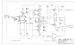
Classe DR4/6 core attached. Dave Reich's stuff ... I don't follow the topology well enough to pass judgement on "innovativeness" but it was some nice sounding gear.
The overall topology isn't innovative, even in 1991 when the schematic was drawn. Douglas Self calls it the generic amplifier configuration, and his particular versions of it are the 'Blameless' amplifiers which you might have heard of. See here for an introduction to possible modifications:
Distortion In Power Amplifiers
You'll quickly see that there are lots of variations on the basic theme.
The Classe circuit you've posted uses cascodes in the first & second stages. Some of the cascode voltages are set by the base current which is unusual (a lot of people will say bad practice) and requires knowledge of the transistor current gain or some way to adjust the cascode voltage. At first glance, the voltage at Q37 emitter looks wrong.
Have fun exploring.
Hi,
Sorry, no.
PM me, I can send you links to two or three "motherlodes", especially for Japanese High End from the majors.
I thought the Phono-Stage was quite cute. This circuit is a generic Op-Amp style, but with cascoding, which is an improvement. The way the cascodes are biased are a bit odd and make them both less effective and more variable due to the tolerances of the transistors used. Bipolar transistors on inputs are really not a good idea IMNSHO.
Have a look at the goldmund Linestage. It was discussed in the goldmund Clone Amp thread... For this type of genre it is probably a very good choice.
Ciao T
Seibundo-Shinkosha sell backissues as far back as Sept 2009. Don't happen to remember the date of the issue in question perchance?
Sorry, no.
I have a small selection of service manuals .pdfs, very helpful for seeing how the "peripheral" details are dealt with, as well as ideas for the core gain stage.
PM me, I can send you links to two or three "motherlodes", especially for Japanese High End from the majors.
Classe DR4/6 core attached. Dave Reich's stuff ... I don't follow the topology well enough to pass judgement on "innovativeness" but it was some nice sounding gear.
I thought the Phono-Stage was quite cute. This circuit is a generic Op-Amp style, but with cascoding, which is an improvement. The way the cascodes are biased are a bit odd and make them both less effective and more variable due to the tolerances of the transistors used. Bipolar transistors on inputs are really not a good idea IMNSHO.
Have a look at the goldmund Linestage. It was discussed in the goldmund Clone Amp thread... For this type of genre it is probably a very good choice.
Ciao T
Phono stage is cute, or that line stage?
In perhaps 70% of discrete preamp circuits I've seen so far, the line stage gain block is re-used for the phono stage, with the simple addition of extra passive components in the feedback loop to initiate the RIAA eq.
The DR4/6, probably because of the complexity of the balanced line stage design used, is a notable exception: the phono stage is a completely different beast, and I would have to say unusual, odd even.
The MM stage alone has no less than 7 DC blocking capacitors in the signal path! Stage after stage of BJTs buffered by JFET source followers. To this day I cannot grasp the rationale for this design.
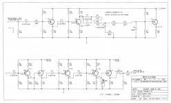
Attachments
Hi,
The phono stage is.
Yes, but I would say that given the dramatically different requirements this is not the best idea.
We would have to ask David Reid for his reasons. Yes, it is odd, but it does introduce some interesting concepts, hence my comment "cute".
First, the J-Fet Buffers do make sense. The whole Phono is open loop and each stage is quite heavily degenerated, giving good linearity but low gain.
An extreme opposite example would be Alex Nikitkin's designs. His style you can make a single stage, MC capable Phono with 3 J-Fets.
If you use a 2SK170BL at Idss you get around 40mA/V transconductance... Use a second J-Fet as Active load and you can easily get 1MOhm load, giving a "near DC Gain" of around 92dB, which if you use this 1M Load as LF determinant of the RIAA EQ allows 72dB Gain. Add a third J-Fet as buffer/follower and you are done.
Supreme simplicity and elegance, sadly polarity inverting...
I have been thinking of a somehawt similar apprach but using the J-Fet as buffer for a common base BJT with active load. This gives a Non-Inverting circuit, but is more complex...
Ciao T
Phono stage is cute, or that line stage?
The phono stage is.
In perhaps 70% of discrete preamp circuits I've seen so far, the line stage gain block is re-used for the phono stage, with the simple addition of extra passive components in the feedback loop to initiate the RIAA eq.
Yes, but I would say that given the dramatically different requirements this is not the best idea.
The DR4/6, probably because of the complexity of the balanced line stage design used, is a notable exception: the phono stage is a completely different beast, and I would have to say unusual, odd even.
We would have to ask David Reid for his reasons. Yes, it is odd, but it does introduce some interesting concepts, hence my comment "cute".
The MM stage alone has no less than 7 DC blocking capacitors in the signal path! Stage after stage of BJTs buffered by JFET source followers. To this day I cannot grasp the rationale for this design.
First, the J-Fet Buffers do make sense. The whole Phono is open loop and each stage is quite heavily degenerated, giving good linearity but low gain.
An extreme opposite example would be Alex Nikitkin's designs. His style you can make a single stage, MC capable Phono with 3 J-Fets.
If you use a 2SK170BL at Idss you get around 40mA/V transconductance... Use a second J-Fet as Active load and you can easily get 1MOhm load, giving a "near DC Gain" of around 92dB, which if you use this 1M Load as LF determinant of the RIAA EQ allows 72dB Gain. Add a third J-Fet as buffer/follower and you are done.
Supreme simplicity and elegance, sadly polarity inverting...
I have been thinking of a somehawt similar apprach but using the J-Fet as buffer for a common base BJT with active load. This gives a Non-Inverting circuit, but is more complex...
Ciao T
I'm going to re-open this thread by asking a potentially stupid question, but bear with me I have my reasons.
Reading up on jFETs, I understand that unlike BJT the basic configuration precludes the production of complementary devices. Currents in BJTs are controlled by a p-n junction, which, reversed, is still a p-n juction involving both holes and electron transport. Currents in jFETs are controlled by the doping level in a chunk of p or n type silicon. For p type devices holes are the majority carrier, for n type devices electrons are, and the mobilities of the two are not identical. So while you can get "close" to compensating for the difference in mobility in your "complementary" devices, it's a much rougher approximation than it is in BJTs.
Matched jFETs, on the other hand, while still a more difficult proposition than bipolars, are doable, especially when thermally coupled.
In practical terms this means that long-tailed pairs are in, but diamond buffers are out.
So here's the question:
For a medium impedance application like sitting behind a 50k audio taper volume pot, what can I expect to hear in the way of differences if I were to hypothetically swap out the BJT input transistors of an op amp circuit for matched jFETs?
I'm investigating the matter myself by op amp swapping, but I'd like to aggregate some opinions on this as supplemental info...
Hi,
2SK389 and 2SJ109 are pretty decently complementary and can be used thusly if desired (John Curl does), as are 2SK170/2SJ74.
In practical terms there is no point of diamond buffers with J-Fet's. Simply take an N-Channel and a P-Channel J-Fet matched for the current at the desired voltage and connect them sources to sources, gates to gates and the two drains to the two rails and you have a nice Buffer.
I have a load of 2SK170/2SJ74 pairs selected for this kind of Job. They are all around 9mA Idss so they can make a Class A/B output buffer with around 12 Ohm output impedance, a maximum of 18mA Class A current and +/-24V Rails, meaning we can drive 1K loads in Class A. Erno Borbeley measured this follower having 0.0074% THD when driving 10K to 5V RMS.
I find J-Fet's give more natural, less strained sound. For example taking a Naim Line stage and replacing the input BJT (and other associated parts) with a J-Fet direct couple dto the pot retained all the positive things about Naim (driver, energy) but it to away the harshness and glare.
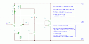
I would recommend a J-Fet Op-Amp circuit using 2SK389 or LSK389 or matched 2SK170/2SK371 as differential Amp, preferably with a CCS tail (another 2SK170/2SK371 - leftover from matching?). This can be realised with one resistor to set the CCS current and two for the load. Input Stage current at 3mA should be ok.
Use either PNP BJT or P-Channel J-Fet in a Lender Circuit as VAS with another 2SK170 as CCS load for the VAS. Again, this needs minimal numbers of Resistors, only one for the CCS and a load, if we want to pad down the open loop gain. I would look at getting a current near Idss for Fet so maybe 9mA.
If we take a 1V dropout from the rail and a PNP Transistor (say 2SA970) we get a Diode in series with 330 Ohm for the load of the +input (delete diode if using 2SJ74) and 82 Ohm for the load of the inverting input. Base/Gate to Drain of +Input, Emitter/Source to Drain of -Input.
CCS to the negative rail with 2SK170 at Idss.
From the output node of the VAS use a 2SK170/2SJ74 follower.
If we want to avoid to use a 2SJ74 in the follower, a single ended follower may be used emplying a matched 2SK170 Pair, one Fet as follower the other as CCS to the negative rail. Such a follower is limited to Class A lone and hence is limited to lighter loads (no less than 2K).
The Transconductance into the VAS Output node will be around 63mA/V (regardless of J-Fet or PNP Trasistor VAS), the 2SK170 as CCS run at Idss has around 8K impedance, so open loop gain will be around 54dB, without additional compensation the -3dB open loop point will be around 150KHz (or 53MHz GBWP). Linear input range should be around 0.8V Peak-Peak.
We could use different CCS for the VAS load, cascode the 2SK170 etc. to give more open loop gain, but this detracts from the simplicity of this circuit. In theory the 2SJ74 in the output (and VAS if used) limits the rails to +/-12.5V to not exceed ratings. In practice others (like Fred Forsell) use the 2SJ74 at much higher rails in the same kind of circuit.
Attached the principle schematic, note this is neither build or simulated, just calculated and drawn "on a cocktail napkin" and may need work/adjustment for best performance, however in the most basic sense of the word it should work.
It is easy to extend this circuit to be rail-symmetric using 2SK389/2SJ109 inputs (for those who are lucky enough to have these in their stash), 2SJ74/2SK170 VAS and the same output buffer, but that is left as an exercise for the reader.
Ciao T
Matched jFETs, on the other hand, while still a more difficult proposition than bipolars, are doable, especially when thermally coupled.
2SK389 and 2SJ109 are pretty decently complementary and can be used thusly if desired (John Curl does), as are 2SK170/2SJ74.
In practical terms this means that long-tailed pairs are in, but diamond buffers are out.
In practical terms there is no point of diamond buffers with J-Fet's. Simply take an N-Channel and a P-Channel J-Fet matched for the current at the desired voltage and connect them sources to sources, gates to gates and the two drains to the two rails and you have a nice Buffer.
I have a load of 2SK170/2SJ74 pairs selected for this kind of Job. They are all around 9mA Idss so they can make a Class A/B output buffer with around 12 Ohm output impedance, a maximum of 18mA Class A current and +/-24V Rails, meaning we can drive 1K loads in Class A. Erno Borbeley measured this follower having 0.0074% THD when driving 10K to 5V RMS.
For a medium impedance application like sitting behind a 50k audio taper volume pot, what can I expect to hear in the way of differences if I were to hypothetically swap out the BJT input transistors of an op amp circuit for matched jFETs?
I find J-Fet's give more natural, less strained sound. For example taking a Naim Line stage and replacing the input BJT (and other associated parts) with a J-Fet direct couple dto the pot retained all the positive things about Naim (driver, energy) but it to away the harshness and glare.
I would recommend a J-Fet Op-Amp circuit using 2SK389 or LSK389 or matched 2SK170/2SK371 as differential Amp, preferably with a CCS tail (another 2SK170/2SK371 - leftover from matching?). This can be realised with one resistor to set the CCS current and two for the load. Input Stage current at 3mA should be ok.
Use either PNP BJT or P-Channel J-Fet in a Lender Circuit as VAS with another 2SK170 as CCS load for the VAS. Again, this needs minimal numbers of Resistors, only one for the CCS and a load, if we want to pad down the open loop gain. I would look at getting a current near Idss for Fet so maybe 9mA.
If we take a 1V dropout from the rail and a PNP Transistor (say 2SA970) we get a Diode in series with 330 Ohm for the load of the +input (delete diode if using 2SJ74) and 82 Ohm for the load of the inverting input. Base/Gate to Drain of +Input, Emitter/Source to Drain of -Input.
CCS to the negative rail with 2SK170 at Idss.
From the output node of the VAS use a 2SK170/2SJ74 follower.
If we want to avoid to use a 2SJ74 in the follower, a single ended follower may be used emplying a matched 2SK170 Pair, one Fet as follower the other as CCS to the negative rail. Such a follower is limited to Class A lone and hence is limited to lighter loads (no less than 2K).
The Transconductance into the VAS Output node will be around 63mA/V (regardless of J-Fet or PNP Trasistor VAS), the 2SK170 as CCS run at Idss has around 8K impedance, so open loop gain will be around 54dB, without additional compensation the -3dB open loop point will be around 150KHz (or 53MHz GBWP). Linear input range should be around 0.8V Peak-Peak.
We could use different CCS for the VAS load, cascode the 2SK170 etc. to give more open loop gain, but this detracts from the simplicity of this circuit. In theory the 2SJ74 in the output (and VAS if used) limits the rails to +/-12.5V to not exceed ratings. In practice others (like Fred Forsell) use the 2SJ74 at much higher rails in the same kind of circuit.
Attached the principle schematic, note this is neither build or simulated, just calculated and drawn "on a cocktail napkin" and may need work/adjustment for best performance, however in the most basic sense of the word it should work.
It is easy to extend this circuit to be rail-symmetric using 2SK389/2SJ109 inputs (for those who are lucky enough to have these in their stash), 2SJ74/2SK170 VAS and the same output buffer, but that is left as an exercise for the reader.
Ciao T
Attachments
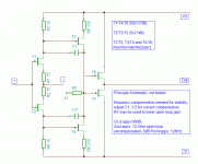
BTW,
Current feedback circuitry is also easily possible. Attached a quick "back of the earlier cocktail napkin" design for that.
If the -Input is grounded or uses a low enough impedance (< 10 Ohm) the open loop gain approaches 68dB, though overall a lot more degeneration is present, so transconductance is lower.
Around 3V of each rail are dropped out by the circuit, so 15V rails would allow 24V peak-peak or 8.5V RMS output.
Another fun fact about this circuit is that it may be operated without feedback loop.
Use a suitable value of R7 and of a resistor from -in to ground and you an open loop circuit. If we make R7 5.1K and desire 12dB gain the resistor from -in to ground would be around 3.6K. In this case omit the compensation capacitors, bandwidth will be around 200KHz...
Gain then scales with the resistor from -in to ground.
Ciao T
Attachments
Personally I'd probably stick J500 CCS into the tail.
Ciao T
I believe the Vishay J500 series are now obsolete, BTW. Other companies make these kinds of things now. I didn't even know about constant current diodes. Thanks for the tip.
- Status
- This old topic is closed. If you want to reopen this topic, contact a moderator using the "Report Post" button.
- Home
- Source & Line
- Analog Line Level
- DIY build of the Pioneer C-21 preamplifier