For me, 1978. SPICE ran on the company mainframe in a glass-walled, raised floor, air conditioned, limited access room. We ran SPICE2 version D (pre 2G6!), and yes it ran from decks of punched cards. Fortunately there was an '026 keypunch that engineers (rather than trained keypunch operators) were allowed to use. Hand your deck to the SysOp, make sure your JCL included a comment with your phone extension number! Come back 2-3 hours later for the results: a 2-inch-thick stack of fanfold printer paper. Then whip out your colored pencils and connect the dots.
At the time, DRC still was done with plots, rulers, eyeballs, adhesive dots, and summer interns.
At the time, DRC still was done with plots, rulers, eyeballs, adhesive dots, and summer interns.
Even today I get this funny feeling when I view a netlist.
Actually didn't like schematic entry when it first came around.
Velum schematics with reference designators blank until the last minute.
My employer still requires schematics with "not used" and "last used" only a few of us remember the actual need.
Problem today is you cant blame a bent corner.
Thanks for the memory lane
-Antonio
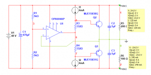
Since the opamp output bias point is halfway between the rails, you don't need or want a Rail-To-Rail-IO opamp. Since you don't need to swing the opamp output very far at all, you can run the opamp using lower voltage supply rails, created via a pair of zener diodes or a pair of LM7812 3-terminal regulator ICs. With less voltage between the opamp supply rails, you can use those zippy 350 MHz opamps like the LM7171, that don't go up to nosebleed supply voltages.
And since you're not swinging the opamp output very far at all, you can use monolithic Darlingtons for the emitter followers, without compromising output swing. If you wish. My railsplitter pcb uses TIP142/TIP147.
Me, I'd prefer series resistors in the emitter legs, plus a bias splitter ("VBE multiplier"), just to set up a known amount of standing bias current in the output stage.
Last edited:
Mark,
Would you be kind enough to show us your variation of this rail splitter. I think I understand what you, Jack, and Richard are saying but I'm trying to visualize all the connections.
Yes, I know it's been awhile, look on the bright side, it's only taken me
this long to catch up.
Cheers,
Would you be kind enough to show us your variation of this rail splitter. I think I understand what you, Jack, and Richard are saying but I'm trying to visualize all the connections.
Yes, I know it's been awhile, look on the bright side, it's only taken me
this long to catch up.
Cheers,
Nope, it's gone forever. More to the point: my interest in this topic has diminished greatly; I now prefer to either use a dual secondary transformer + linear PSU, or an AC wall wart + dual halfwave rectifiers + dirt cheap ripple eliminator ICs. Rail splitters are so last century.
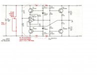
Here are changes based on the thread discussion of the rail splitter.
Since we moved R2, R3 from emitter to the rails, then it was suggested to the middle; I didn't know which would be better X1, Y1 or X2, Y2...assuming farther down the rails to follow on nodes not marked...X3, Y3, then X4, Y4, then at the load...X5, Y5.
Nuts, here I am lost in last century elevated flooring, JCL, punch cards, boxes of them
that I spent hours and days getting it just right, and then going to the lab with
the punch card readers, I saw that gal again and she took my breath away,
oops, I walked into the stair railing and whoosh, all my beautiful punch cards
tumbled out of the box, over the railing, being blown about like the red balloon.
I hear the song...dust in the wind.
I think I saved the schematic.
Happy Thanksgiving,
Attachments
Last edited:
Honestly I'd leave R2, R3 where they are drawn in the schematic for now, or maybe move them in the other direction.Since we moved R2, R3 from emitter to the rails, then it was suggested to the middle; I didn't know which would be better X1, Y1 or X2, Y2...assuming farther down the rails to follow on nodes not marked...X3, Y3, then X4, Y4, then at the load...X5, Y5.
However, there's one big question that has to be addressed - where's your input coming from?
Is it a floating transformer supply? In this case, leave things as they are.
Or is it an existing unipolar supply? Then parallel an electrolytic cap to whichever of R2/R3 goes to the "clean" side (ground).
Adding a buffer to this would be much the same as in a headphone or speaker driver, really. It would be good to know how much current you'll need, since I suspect a single emitter follower with BD139/140 (MJE340/350) or similar would be plenty in many cases and getting it stable thermally and electronically ought to be far easier than for a Darlington.
- Status
- This old topic is closed. If you want to reopen this topic, contact a moderator using the "Report Post" button.
- Home
- Source & Line
- Analog Line Level
- Op Amp Rail Splitter Question