@Mooly
The question whether it would be subjectively better is fallacious imo, without defining for what purpose. In order to create an effects box, it might be interesting, e.g. for distorting a guitar, or to emulate a WAVAC without spending 350K. In audio, I think it is a safe bet that all distortions that are not there make it better.
vac
That's a fair and valid comment and one I used to subscribe to.
Over the years I found my view changed on that though when I kept preferring "less perfect" designs over the more technically perfect.
Being so encouraged with the results during testing I have gone ahead and altered my preamp to use this technique and am now in the long process of evaluating the result subjectively.
Experience has taught me to be wary of jumping to conclusions when doing work like this, but here there does seem to be quite a marked difference subjectively.
The initial impression (which has remained) is of a much more "solid" and stable image... the lower and mid registers being where this really stands out. This retains (and seems to build upon) the wonderful 3d presentaion which the amp as a whole is capable of.
Getting the resistors just right was not easy as breadboarding a test set up and even making a "point to point" model showed how stray capacitance affects the final result.
In the end I used pots to get an initial value and then replaced with fixed resistors. R7 and R8 are the new components.
The modified version is here,
Attachments
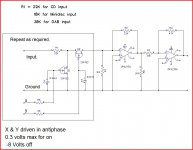
I set up two OPA134's as shown in the circuit below.
The beehive trimmer cap was adjusted for good compensation of the first opamp (top scope trace in all following shots) at 40 Khz and 10mv pk pk output.
The resistor Rx on the second opamp was adjusted to give an identical waveform compared to the conventionally compensated opamp above. The value of Rx was 1950 ohms. The traces could be overlaid with no difference showing at 10 mv pk-pk output.
These shots show the output at 40 khz and 10 mv pk-pk and also at 1Mhz and 10 mv pk-pk. As can be seen the results appear identical.
The ringing and instability is caused by too much loop gain combined with too much phase shift.
With the C you correct the phase shift.
With the resistor between the inputs you sqash the loop gain.
So both methods solve the problem.
However, with the resistor you increase what is known as the noise gain, which indeed does what it says.
Also, because the resistor squashes the loop gain, your distortion will get much worse than with the cap solution.
jan
Also, because the resistor squashes the loop gain, your distortion will get much worse than with the cap solution.
Distortion is not everything
") .
.The ringing and instability is caused by too much loop gain combined with too much phase shift.
With the C you correct the phase shift.
With the resistor between the inputs you sqash the loop gain.
So both methods solve the problem.
However, with the resistor you increase what is known as the noise gain, which indeed does what it says.
Also, because the resistor squashes the loop gain, your distortion will get much worse than with the cap solution.
jan
Thanks Jan... I can't argue with anything you say here, and yes, as you say I have thrown performance away and worsened the ultimate distortion and noise level although my ears are telling me it is a change for the better.
Distortion is not everything
I used to think it was, along with SNR and damping factors and extended frequecy response and low noise... but the last 10 yrs or so have seen me revise my views on this.
I would just say to anyone contemplating or wanting to try this that it is essential to test test and test again along the way. My testing of this showed that the ultimate values are quite critical and you can't guess or approximate. Every opamp type will be different too.
I missed this thread first time around.
I wonder what providing a bit of both compensations would do for technical and sound performance?
Say, find the minimum cap value for cap only comp and fix at half this value. = under-compensated.
Then find the biggest resistor value that provides the remainder of the compensation to avoid the overshoot and any subsequent ringing.
Going back to the highlighted non linearity in post13.
I see similar ringing in the triangulated 1MHz signal in post12. It appears less bad in the -ve peak of the waveform.
I missed this thread first time around.
I wonder what providing a bit of both compensations would do for technical and sound performance?
Say, find the minimum cap value for cap only comp and fix at half this value. = under-compensated.
Then find the biggest resistor value that provides the remainder of the compensation to avoid the overshoot and any subsequent ringing.
Going back to the highlighted non linearity in post13.
I see similar ringing in the triangulated 1MHz signal in post12. It appears less bad in the -ve peak of the waveform.
I wish I could turn up more info on this. Nelson Pass in the thread linked to in post #1 (where I first saw the technique) just generalises on it with no specific examples. I tried to get a bit more info...
but no luck.I see what you mean about the shot in post #12. All the amplitudes were small and it's possible some artifact made itself apparent in the measurements. I wouldn't like to say that was instability in the opamp. I sometimes notice miniscule effects on say shorting scope probes together and then touching that to a grounded signal generator, not to mention to 0-30 v PSU's.
I am about to start investigating this on an F5 or F5x................ provide.................... the compensation to avoid the overshoot and any subsequent ringing..........
Wish me luck, or could it be a flash of miracle issuing?
According to the Member I am in dialogue with, it seems that 20% to 25% overshoot on fast signals is the norm, for an F5 and builders/listeners just accept that !
Last edited:
I am about to start investigating this on an F5 or F5x.
Wish me luck, or could it be a flash of miracle issuing?
According to the Member I am in dialogue with, it seems that 20% to 25% overshoot on fast signals is the norm, for an F5 and builders/listeners just accept that !
It would be great to know what you think subjectively in doing this mod.
When we talk of fast signals and overshoot I suppose in some ways the fast rise times from a generator are unrealistic compared to anything an audio source can put out. An NE5532 buffer shows this effect when built even with say 10k resistors and yet many designers would never apply compensation in that situation. Add an input filter to limit the slew rate and the perceived problem fades away.
It will be interesting to know your findings Andrew.
An op amp rated for unity gain operation should be stable with little overshoot error. I would start (assuming a UGS device) by firstly isolating the output load by using a 47 or 50 Ohm resistor. Second step would be to provide some HF roll off on the input - so for example -3dB at 100KHz. I would not expect to see any overshoot or response anomalies on such a set up. Of course, if you are trying to reduce the loop gain, the the techniques escribed by Mooly are absolutely correct. But why use an opamp if you feel low loop gain is the way to go?
Some good reading on lead-lag compensation:AN1604 from National. It is also treating the single resistor case and gives a design methodology for the RC network.
I plan to test this very soon in practice (waiting for the parts)...The goal is to stabilse a LM4780 to a gain of ~two, see if it works OK...
I plan to test this very soon in practice (waiting for the parts)...The goal is to stabilse a LM4780 to a gain of ~two, see if it works OK...
that app note's "lead-lag compensation" is "noise gain compensation" - I find the lead, lag terminology can be confusing
since the "lead"+"lag" mostly cancel their respective phase adjustment functions the net result is to change the gain at the intercept frequency - so I think the "noise gain" name is more descriptive of what is achieving the compensation
but it is useful to have terminology that differentiates between full bandwidth noise gain increase with the R vs the series R,C that lets you keep more low frequency loop gain
I'm with AndrewT on multiple, smaller, compensations being, possibly, less audible than 1 fell swoop.
However, my take on this is going to be very strange, involve (mis)use of diodes and is mostly voltage activated instead of current activated.
On a Circlophone (ltp) that does have a feedback cap, RF filter cap, output RC, I added my new accessory: http://www.diyaudio.com/forums/atta...1613-my-little-cheap-circlophone-softclip.gif
It is from in+ to in- but its not exactly a resistor. I wish to take a moment to note that the diodes are capacitive and that RC multi-pass is present.
For reference point, the Circlophone amp is using a 20+20vac transformer and is set for very high gain with a 22k feedback resistor with the dynamics up in similar proportion. . . but otherwise, the amp is a match for the standard edition.
Prior to installing my accessory, the low volume pitches had level response but loud playback got darker as if treble roll off.
After installing my accessory, the low volume pitches and loud playback have similar treble with no observable difference.
However, the soft clip function is not significantly effective (as intended, else you hear it switch).
The most noticeable benefit is that loud playback is at considerably higher resolution than it was previously.
That last effect looks like a near miss match to Mooly's description of resistor from in+ to in-.
The accessory was necessary for my application when after discovering the consequences of setting Circlophone to far higher gain, it became so dynamic that the volume control dial was nearly useless AND both low volume and loud playback will occur on a single track. The tone shift between quiet and loud was disturbing when repeatedly occurring in the middle of songs. The accessory fixed it and the tone is level no matter if quiet or loud--same tone.
The Circlophone and its in+ to in- accessory remain together and in active service. I consider it less expensive than concert tickets and the audio is comparable. I don't always want something to show off big, but when I'm in the mood for that, I use this amp for it.
Last edited:
I'm not sure, but we might be on the same track.
Wish I knew what that was.
Both the resistor and my crazy circuit causes bigger soundstage and greater clarity at the expense of more forwards tone. With the power op-amp, this can be unscrewed by using bigger amp board decoupling caps; however, we need an amp that naturally wants small caps, as a starting place I got one! non-inverting TDA7294 wants a pair of 220u in addition to a rail to rail RCR of 2u. Well, we could replace those 220u with 470u (low esr compact type) to straighten out the harmonic frequency response caveat.
No idea if this will work.
But also integrated amp boards (power supply is aboard with the amp) could be used since amp board decoupling is as huge as the reservoir and therefore these extra dull things might could be perked with your resistor idea. Although these are more ideally fixed on the power-side, one could use that type amp for any sort of "perk-up" experiments for which it has excessive tolerances.
So, if you happen to have either sort of power amp available, or even a discrete amp that wants 100u amp board decouping caps (that you can replace with 220u or 330u low esr type), then you might try the resistor trick with a power amp to see if it will put on a show.
In some cases, we might have to decrease the gain, adjust the feedback current and/or adjust the other compensations.
Good luck with your nobel endeavors for sound stage, since THAT artwork is the tallest order for an audio amp.
I was a bit upset to discover that the scope was utterly blind to an audio amplifier's most difficult task. Is it impossible to measure electronically?
I believe that soundstage promotion of an audio amplifier is best observed in monophonic so that stereo separation doesn't pollute the observations.
P.S.
If you want to demonstrate epic soundstage at the expense of other factors, the answer is quick, easy, daft, inexpensive, and right here: Bridged TDA2003 (mine is run from regulator)
When I asked KeanToken what means that amplifier could possibly have for hi-fi class soundstage he replied: "Singleton on regs. Of course." as if it was totally expected.
Mooly, I propose that you and I have hindered some part of the LTP for much the same effect, and I propose exploring NTP and SSA inputs as an alternative.
Sorry, but I cannot guess much further, except:
All of the experiments need to use regs/k-multi/capmulti so that the LTP doesn't throw the baby out with the bath water from power noise in the feedback loop and so the singleton doesn't amp power noise. Somehow that is all related and highlights a need to subtract power noise prior to making comparisons.
And, finally, I've run out of guesswork.
Would be nice if the scope showed something on the topic though, since guess, try, repeat, is a bit slow.
I want to know who's going to be the first to measure meaningful soundstage, and say congrats on the groundbreaking head start.
Last edited:
Then do it with only one speaker and you'll be sure.As far as I know what is called, "sound stage", is related to cross talk between stereo signals, exactly what anything in this topic has to do with that I am not sure.
rcw
Principally, yes but the presence or not of small amounts of low order, upper mid-treble distortion products has much to do with enhancing the apparent image sharpness - nothing to do with add-on stereo width circuits though. The results can be intentional or serendipitous as any user or sensible modder of old but still popular models will attest..... "sound stage", is related to cross talk between stereo signals......
This is just one strategy for subjectively improved stereo imaging. It can be very impressive and result in big ticket sales if you get it right for your product and target audience.
Does this remain true regardless of the number of channels? For example, mono, stereo, trio, surround, etc. . .? I've found that if I make the soundstage judgements in monophonic first, then, later, when I connect more channels, the imaging is extraordinary. Simply put, that's because it was extraordinary in monophonic.Principally, yes but the presence or not of small amounts of low order, upper mid-treble distortion products has much to do with enhancing the apparent image sharpness - nothing to do with add-on stereo width circuits though. The results can be intentional or serendipitous as any user or sensible modder of old but still popular models will attest.
I wonder what type "small amounts of low order, upper mid-treble distortion products" are generated by resistor (or resistor series to diodes) across the LTP from IN+ to IN-? Is there some specifics on the type?
I didn't know about that. Previously I had assumed that all you needed was phase linear to beyond 1mhz, a "just right" amount of compensation, and a very sharp square wave test with just barely a hint of acutance pattern but never rounded.
P.S.
The only case I've seen where noise was beneficial was for post processing MP4, Itunes, HDradio and similar/same types of codecs. Some people get headaches from those, and triode harmonic distortion removes the headache problem without really disturbing the ear. But, that is oddly a case of noise cancellation. Are we looking at something similar here?
- Status
- This old topic is closed. If you want to reopen this topic, contact a moderator using the "Report Post" button.
- Home
- Source & Line
- Analog Line Level
- A Different Opamp Compensation Technique.