Aside form output drive capability, are there any input or internal differences (like margins or latching) that need some clarification?
That I don't know.
The TI "LM833" should be the same as their take on the MC33078 (which is actually a beefed-up version of the original part, though given the gain/phase graph in the datasheet I'm not sure whether it's as well-behaved). As it happens, Samuel Groner measured both this one and the NatSemi LM833. The "33078" is good input-wise, especially for a cheapie, but badly in need of some Class A bias.
BTW - I'm still not sure how exactly the LM833 VAS / output stage bias arrangement works. Has anyone looked at that?
BTW - I'm still not sure how exactly the LM833 VAS / output stage bias arrangement works. Has anyone looked at that?
I couldn't quite believe it either but it really does seem to be the case. I can't just think of any part where its 'different different' yet retaining the same base number. Package differences, temp range, yes, but not a change to the internal structure.
The later second sourced TI version is massively better in its drive ability... and if it really does use a quasi output stage then the distortion spectrum is probably going to be totally different as well.
Maybe the TI active volume control would reveal differences")
Do both meet the same datasheet? That would be 'ok' from a marketing pov.
And if they do, who cares about the internal structure from the view of a designer who designs-in the 833 based on data sheet guaranteed minimum values.
Basically that's good engineering practice.
Jan
Last edited:
LM833P and LM833N Measurements
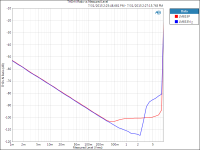
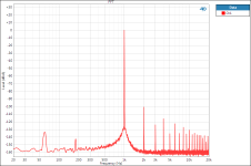
I measured the distortion of both types of LM833 today. The "TI" version will be referred to as LM833P and the "National" version will be LM833N. For testing the parts were configured for unity gain, +/-15V power supplies, and an Audio Precision APx555 was used for testing (measurement bandwidth was 90kHz). To determine differences in the output current capabilities of the parts, a 60o ohm load was placed on the output.
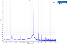
Below about 2Vrms, into a 600 ohm load, the LM833N has the advantage. Looking at the FFT at 1kHz, 2Vrms, the LM833P shows a large amount of higher harmonics which are not present in the LM833N. However, this picture totally changes at higher amplitudes where the LM833N begins to show greater distortion (refer to FFTs at 4Vrms).
In all images:
Blue curve: LM833N
Red curve: LM833P
Edit: The test conditions are given in the image title, so hover your mouse over the image for test conditions.
I measured the distortion of both types of LM833 today. The "TI" version will be referred to as LM833P and the "National" version will be LM833N. For testing the parts were configured for unity gain, +/-15V power supplies, and an Audio Precision APx555 was used for testing (measurement bandwidth was 90kHz). To determine differences in the output current capabilities of the parts, a 60o ohm load was placed on the output.
Below about 2Vrms, into a 600 ohm load, the LM833N has the advantage. Looking at the FFT at 1kHz, 2Vrms, the LM833P shows a large amount of higher harmonics which are not present in the LM833N. However, this picture totally changes at higher amplitudes where the LM833N begins to show greater distortion (refer to FFTs at 4Vrms).
In all images:
Blue curve: LM833N
Red curve: LM833P
Edit: The test conditions are given in the image title, so hover your mouse over the image for test conditions.
Attachments
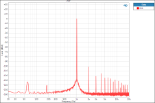
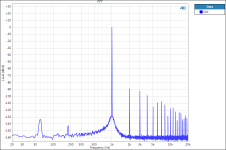
That's terrific John, thanks very much. The 'P' version certainly seems to have the classic quasi trait of even harmonics predominating in a more obvious manner than the 'N', and particularly I'm looking at the 7th harmonic at 4vrms (isn't the 7th reputed to be the audio nasty one ?)
At lower levels though, which is where most opamps live, the old 'N' does actually seem pretty stellar in comparison. Does the 'P' have the sonic edge though. All very interesting.
Thanks again for putting the time in on these.
At lower levels though, which is where most opamps live, the old 'N' does actually seem pretty stellar in comparison. Does the 'P' have the sonic edge though. All very interesting.
Thanks again for putting the time in on these.
I've wondered for awhile why no one has used this approach on the LM3886, it should be fairly simple to stabilize that part for low gains using a noise gain approach. I used a similar technique to stabilize difference amplifiers here: http://www.ti.com/lit/an/slyt630/slyt630.pdf
While not with the 3886, I have a bunch of 7293's in my possession that I plan on doing exactly that--taking them from a datasheet-minimum G=20 down to G=12 with HF noise gain. We'll see how it goes, seeing as there's no UGBW spec for the 7293 (I admire the details and information presented in the 3886 datasheet).
So it'll be a few hot dates with the oscilloscope. Hopefully not *too* hot.
re post66, distortion comparisons:
The Ti 833P seems to have a distortion floor at around -100dB irrespective of the output voltage/current. That is until noise obscures the data.
The Nat 833N has a lower distortion when output current is <5.5mApk. Going down to -114dB @ 2.3Vac/5.5mApk, before noise hides relevant data.
Is it correct to assume that the Ti833P is useful when one knows that higher current is the predominant output and in this region of >5.5mApk the distortion results show better performance?
The corollary being that if one knows that output current rarely, or never exceeds 5.5mApk, then the Nat 833N gives the lower distortion.

If i am mistaken, please excuse me, but i have read material in this thread and someone mentioned here with the Rx between +and- in inverting configuration places sounds more in between the speakers, middle.
I have experienced this situation heavily when placing 1000pf capacitor between + and - inputs of NE5534, inverting configuration.
Lately, almost a year for now, fiddling with Tidu34, finally i got some proof that even a compensation capacitor along with different small value (10-100nf) decoupling caps have a huge impact on soundstage.
Also input filter is playing a huge role.
A lot of different way for decoupling, compensation and input filters were used and as a result, something was always wrong... mostly the rhythm:
You may have a Huge soundstage, cool vocals, deep bass.. but interaction of audio frequencies between each other(low and high) are so "out of phase" that it makes you feel the recordings ARE BAD.. but its not true.
Coming to conclusion, problems can't be fixed by doing Rx compensation. If your layout, feedback compensation and decoupling are adequate for a specific opamp/circuit, then there will be no need for it at all.
In the end, picture must be viewed as a whole
Here is the Nazar half circuit: http://www.upload.ee/image/5351187/lololo.png
Very huge impact on center imaging.
Last edited:
- Status
- This old topic is closed. If you want to reopen this topic, contact a moderator using the "Report Post" button.
- Home
- Source & Line
- Analog Line Level
- A Different Opamp Compensation Technique.