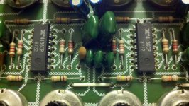
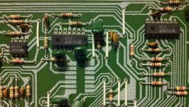
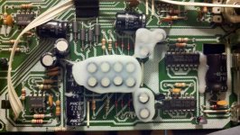
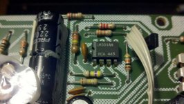
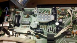
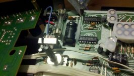
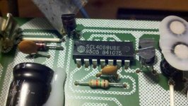
Hello everyone, I am very new to the world of proper electronics. I can conduct basic repairs on amplifiers and simple things, but I am not satisfied with that. I want to learn more. I want to make things better. Make them the way they should have been. I caught wind of a few guys "modding" amps, HUs (head units), passive crossovers, etc.. with basic opamp upgrades, mosfet improvements, and cap replacements. I will admit I do NOT know the BETTER brands that will give the better results. I do NOT know the electronic skill set that it takes to upgrade the uF or V of a particular peripheral to gain a specific desire. However I am willing to learn. Attached below are pics of the guts of an old school active Audio Control EQX. This thing will be used in an SQ setup for next seasons SQ/SQi car audio competition. My goal is to make it cleaner and warmer than it has ever been.
Attachments
-
 2011-08-10_21-38-21_780.jpg55.3 KB · Views: 60
 -
 2011-08-10_21-37-58_624.jpg65.3 KB · Views: 61
 -
 2011-08-10_21-37-50_782.jpg65.7 KB · Views: 67
 -
 2011-08-10_21-39-06_718.jpg78.9 KB · Views: 37
 -
 2011-08-10_21-38-55_139.jpg86.5 KB · Views: 67
 -
 2011-08-10_21-38-35_405.jpg68.9 KB · Views: 63
 -
 2011-08-10_21-41-41_69.jpg61.9 KB · Views: 40
 -
 2011-08-10_21-40-19_644.jpg58.5 KB · Views: 32
 -
 2011-08-10_21-39-43_637.jpg68.2 KB · Views: 36
Hi ,
I think it's quite impossible to do any improvement on that circuit .
I see the stamped numbers on the ICs , it belongs to the Eighties .
I don't know absolutely nothing about car ,SPL etc. but basic rule tells
me that 'less is better' ,'cos every added circuit in the signal path brings noise and distortion ,so in the end what that EQ/Xover adds , it also takes something.
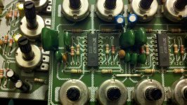
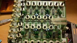
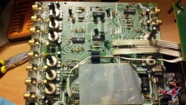
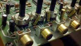
Well , I guess it has also the electronic Xover feature ,because I see a pair of RCAs at the input and a lot of outputs ,or maybe it splits the signal to front and rear ...
Changing the input and output and interstage coupling (if any..) caps ,which are
electrolytics ,to some film -polypropilene caps would only reveal a little better what the mess of circuits is sourcing
I think it's quite impossible to do any improvement on that circuit .
I see the stamped numbers on the ICs , it belongs to the Eighties .
I don't know absolutely nothing about car ,SPL etc. but basic rule tells
me that 'less is better' ,'cos every added circuit in the signal path brings noise and distortion ,so in the end what that EQ/Xover adds , it also takes something.
Well , I guess it has also the electronic Xover feature ,because I see a pair of RCAs at the input and a lot of outputs ,or maybe it splits the signal to front and rear ...
Changing the input and output and interstage coupling (if any..) caps ,which are
electrolytics ,to some film -polypropilene caps would only reveal a little better what the mess of circuits is sourcing
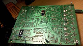
Few more pics:
Attachments
-
 2011-08-10_21-41-46_693.jpg48.2 KB · Views: 33
 -
 2011-08-11_15-08-45_605.jpg52.5 KB · Views: 43
 -
 2011-08-10_21-41-59_202.jpg63.2 KB · Views: 35
 -
 2011-08-11_15-09-17_504.jpg44.5 KB · Views: 29
 -
 2011-08-11_15-09-11_13.jpg56.4 KB · Views: 25
 -
 2011-08-11_15-09-00_370.jpg52.6 KB · Views: 35
 -
 2011-08-11_15-09-58_860.jpg29.9 KB · Views: 33
 -
 2011-08-11_15-09-24_852.jpg51.1 KB · Views: 29
 -
 2011-08-11_15-10-49_390.jpg59.2 KB · Views: 32
Last edited by a moderator:
Hi ,
I think it's quite impossible to do any improvement on that circuit .
I see the stamped numbers on the ICs , it belongs to the Eighties .
I don't know absolutely nothing about car ,SPL etc. but basic rule tells
me that 'less is better' ,'cos every added circuit in the signal path brings noise and distortion ,so in the end what that EQ/Xover adds , it also takes something.
Well , I guess it has also the electronic Xover feature ,because I see a pair of RCAs at the input and a lot of outputs ,or maybe it splits the signal to front and rear ... Changing the input and output and interstage coupling (if any..) caps ,which are electrolytics ,to some film -polypropilene caps would only reveal a little better what the mess of circuits is sourcing
Thank you for the information!! I was thinking of swapping the quad opamps with these:Digi-Key Part Search
and swapping the caps with equal values Elna caps for a warmer sound. I like your last sentence. Love it actually. I want the circuits to reveal the source units output as much as possible as we will be running as clean of a HU as possible. After reading some of you guy's modded DACs on here that is debatable! This forum is amazing. I cannot agree more with your less is better quote. I commonly refer to it as the KISS method I will not waste your time with the names of the circuits your mentioned and I will google them for myself. Thank you for the knowledge and I look forward to being schooled further by others on here.
Jesse
 SPLAudioHz, it is usually best to attach your photos here. Please see this thread:
http://www.diyaudio.com/forums/everything-else/183084-pictures-why-not-attach-them.html
I've attached those in your last post.
http://www.diyaudio.com/forums/everything-else/183084-pictures-why-not-attach-them.html
I've attached those in your last post.
Thanks! I did not know, I guess I am learning more than I thought on here. I will do so from now on.
Yes , we're all learning ,also Pano's learning ...
One month ago I was obsessed that my Marantz Cdp was sounding ugly ,
so I collected some info about its circuits ,like DAC ,output stage ,muting.
In the end I ruined everything ,also because the Pcb traces were so thin and delicate . But I really didn't like how the Piano was 'rendered' ,and the piano is a king instrument .So I changed the 47 uF Electrolytic caps ( good quality ,Elna Cerafine ) to 4.7 uF polypropilene caps ,and it sounded the same .Then I took the signal directly from Dac's output , and it sounded awful .
Then I wanted to add extra stabilized voltage to the Dac , but I blew everything
It had a dual op-amp ( IC ) , a 4565 , as output stage .
Now I listen to Cds with an old Philips , a little more brutal but sincere ...
So I'm not the good one to tell you how to change circuits or swap ICs .
Nowadays I guess that industry uses SMD parts to keep space and size little ,
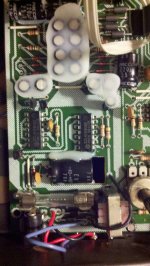
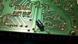
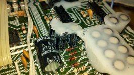
but that EQ has some space available to put some polypropilene -polyester capacitors instead of those yellow 2.2 uF electrolytics at the outputs .
It may be difficult too , to hear any improvement in the change .
You should decribe all the components in the chain and how you intend to use them ...
One month ago I was obsessed that my Marantz Cdp was sounding ugly ,
so I collected some info about its circuits ,like DAC ,output stage ,muting.
In the end I ruined everything ,also because the Pcb traces were so thin and delicate . But I really didn't like how the Piano was 'rendered' ,and the piano is a king instrument .So I changed the 47 uF Electrolytic caps ( good quality ,Elna Cerafine ) to 4.7 uF polypropilene caps ,and it sounded the same .Then I took the signal directly from Dac's output , and it sounded awful .
Then I wanted to add extra stabilized voltage to the Dac , but I blew everything
It had a dual op-amp ( IC ) , a 4565 , as output stage .
Now I listen to Cds with an old Philips , a little more brutal but sincere ...
So I'm not the good one to tell you how to change circuits or swap ICs .
Nowadays I guess that industry uses SMD parts to keep space and size little ,
but that EQ has some space available to put some polypropilene -polyester capacitors instead of those yellow 2.2 uF electrolytics at the outputs .
It may be difficult too , to hear any improvement in the change .
You should decribe all the components in the chain and how you intend to use them ...
That last part is a really good idea!! I am not savvy on what each part is by its technical name, but I will sure try. I like your suggestion to swap those 2.2s out for some higher quality polypropylene caps. that would smooth things out a bit. I am sorry to hear about your mishap with your MarantzYes , we're all learning ,also Pano's learning ...
One month ago I was obsessed that my Marantz Cdp was sounding ugly ,
so I collected some info about its circuits ,like DAC ,output stage ,muting.
In the end I ruined everything ,also because the Pcb traces were so thin and delicate . But I really didn't like how the Piano was 'rendered' ,and the piano is a king instrument .So I changed the 47 uF Electrolytic caps ( good quality ,Elna Cerafine ) to 4.7 uF polypropilene caps ,and it sounded the same .Then I took the signal directly from Dac's output , and it sounded awful .
Then I wanted to add extra stabilized voltage to the Dac , but I blew everything
It had a dual op-amp ( IC ) , a 4565 , as output stage .
Now I listen to Cds with an old Philips , a little more brutal but sincere ...
So I'm not the good one to tell you how to change circuits or swap ICs .
Nowadays I guess that industry uses SMD parts to keep space and size little ,
but that EQ has some space available to put some polypropilene -polyester capacitors instead of those yellow 2.2 uF electrolytics at the outputs .
It may be difficult too , to hear any improvement in the change .
You should decribe all the components in the chain and how you intend to use them ...
 . Those things are everywhere in my area. If you are interested I can keep an eye out for yah. Guys pick them up at garage sales and used them in garages to power old zenuth speakers while they are wrentching on car. lol! Waste I know, but what can I say, I live in the midwest, we have our fair share of rednecks.
No ,ThanksMarantz
Actually , I really don't like the way op-amps work , also the discrete made ones , they still 'operate' with negative feedback (NFB ) circuits ,which I don't like .
That's why I'm dubious about changing electros to film caps , because they'll reveal better the 'inside' troubles of the circuit .
Oh ! never mind
So are you suggesting that I should replace the 2.2s out with some Elnas of the same value or find some higher quality Polypropylene caps? I do not want to cause any damage to anything. However I do not see how I could if I keep the values the same. Not like I would be increasing the resistance. Just altering the material used in the filter.
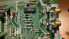
The 2.2 µF value sets the highpass frequency , which would be around ˜10 Hz .
For values till 4.7 µF it's ok to use polyprop or polyester caps instead of electrolitycs because of the size . So if you need to change the highpass frequency point ,you can choose values well under 2.2 µF .Resistor remains unchanged ; also , the circuit that follows would probably have another capacitor at its input.
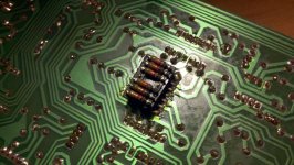
But this is for passive filters circuits . Probably the ACEQX has also a fixed highpass , I mean ,those resistors on the back of the board would suggest that they could be changed if needed .Are those 12 K ?
For values till 4.7 µF it's ok to use polyprop or polyester caps instead of electrolitycs because of the size . So if you need to change the highpass frequency point ,you can choose values well under 2.2 µF .Resistor remains unchanged ; also , the circuit that follows would probably have another capacitor at its input.
But this is for passive filters circuits . Probably the ACEQX has also a fixed highpass , I mean ,those resistors on the back of the board would suggest that they could be changed if needed .Are those 12 K ?
- Status
- This old topic is closed. If you want to reopen this topic, contact a moderator using the "Report Post" button.
- Home
- Source & Line
- Analog Line Level
- New to this so be gentle: Want to mod a Audio Control EQX