Hello,
Im constructing active loudspeaker system with Seas L12 and Vifa XT25. I have already build the box and I want to make HP filter aka excursion limiter from obvious reasons. Standard filters (2nd order L-R, Butterworth, Bessel, 4th order...) have very poor time/transient characteristics in that region and ruin already poor bass performance of the loudspeaker.
But with experimenting with WinISD and Woofer Box and Circuit Designer (FRD consortium rule!) I have found almost ideal filter for this purpose. I have "reversed" Linkwitz Transform filter, ie instead F0 is larger than Fp I have simulated larger Fp than F0. With that changes response completely, namely, instead of gain in lower frequencies we have attenuation ie high pass filter, but with transient/time characteristics (and infinite frequency EQ variations) incomparably better than standard HP filters.
BUT!, thats all simulation and I cant find ANY (on internet and here) system with L.T. implementation done this way. Well if you have practical experience or theoretical knowledge please CHECK if I miss some thing and whether it is REAL this implementation of L.T. filter.
In addition I have uploaded images with comparison of Frequency and Phase response, Xmax, Group Delay with : L/R 4th order - 40Hz (blue), Butt 2nd order - 40Hz (green), Reverse Linkwitz Transform (red) and no filter (white).
FR:
Phase:
Group Delay:
Xmax:
Im constructing active loudspeaker system with Seas L12 and Vifa XT25. I have already build the box and I want to make HP filter aka excursion limiter from obvious reasons. Standard filters (2nd order L-R, Butterworth, Bessel, 4th order...) have very poor time/transient characteristics in that region and ruin already poor bass performance of the loudspeaker.
But with experimenting with WinISD and Woofer Box and Circuit Designer (FRD consortium rule!) I have found almost ideal filter for this purpose. I have "reversed" Linkwitz Transform filter, ie instead F0 is larger than Fp I have simulated larger Fp than F0. With that changes response completely, namely, instead of gain in lower frequencies we have attenuation ie high pass filter, but with transient/time characteristics (and infinite frequency EQ variations) incomparably better than standard HP filters.
BUT!, thats all simulation and I cant find ANY (on internet and here) system with L.T. implementation done this way. Well if you have practical experience or theoretical knowledge please CHECK if I miss some thing and whether it is REAL this implementation of L.T. filter.
In addition I have uploaded images with comparison of Frequency and Phase response, Xmax, Group Delay with : L/R 4th order - 40Hz (blue), Butt 2nd order - 40Hz (green), Reverse Linkwitz Transform (red) and no filter (white).
FR:
An externally hosted image should be here but it was not working when we last tested it.
Phase:
An externally hosted image should be here but it was not working when we last tested it.
Group Delay:
An externally hosted image should be here but it was not working when we last tested it.
Xmax:
An externally hosted image should be here but it was not working when we last tested it.
If you have say a mid in a sealed box with say q=0.5 Fs 90Hz, you can use LT to change to say Q=0.707 Fs 300Hz, thus the mid is now filtered with a classic butterworth rolloff at -3dB at 300Hz (true acoustical output). Add a separate 12dB butterworth stage (after LT) at 300Hz and you end up with an true acoustical output of LR24 at 300Hz -6dB.
You can use this method on the tweeter filtering as well.
Thats how my 3 way active xover is.
I recommended you actually measure the box q/Fs to get accurate acoustical results.
You can use this method on the tweeter filtering as well.
Thats how my 3 way active xover is.
I recommended you actually measure the box q/Fs to get accurate acoustical results.
I'm sorry I was not specific enough last time. The box is bass-reflex (5L, 60Hz) and HP filter is around 40hz, ie HP subsonic filter. The "Reverse" L.T. filter is with values F(0) = 40Hz, Q (0) = 1; F(p) = 80Hz, Q(p) = 1 (red line). In addition I have simulated normal L.T. filter with values F(0) = 80Hz, Q(0) = 1; F(p) = 40Hz, Q(p) = 1 (yellow line). And this, along the other filters, are their responses.
And finally this "Reverse" filter gave me quite realistic component values in True Audio's Linkwitz Transform Circuit Design Spreadsheet.
An externally hosted image should be here but it was not working when we last tested it.
And finally this "Reverse" filter gave me quite realistic component values in True Audio's Linkwitz Transform Circuit Design Spreadsheet.
An externally hosted image should be here but it was not working when we last tested it.
Sadly, most people really don't know much about the "Linkwitz Transform". This circuit is a member of a class of circuits known as "biquadratic filters". The name arises because the transfer function is the ratio of two quadratic functions in s. Unfortunately, many state variable filters are called "biquads", which is confusing because they do not implement a biquadratic function and only have a quadratic denominator like other second order filters. Mr. Linkwitz simply invented the classic circuit to implement a biquadratic filter, and then promoted it for audio use, so his name became associated with it. There are many other circuits for implementing this type of filter.
A biquadratic filter can take on a bunch of "shapes". The best known is the one where the low frequencies are boosted more than the high frequencies (e.g. used to extend the low end of a sealed subwoofer), however the opposite can be true. In fact you can use a biquadratic circuit to create something like a second order EQ section, where the high and low amplitude limits are at the same level. You can even use it do perform baffle step equalization, something that was pointed out to me last year by Jeff Bagby over at the Parts Express tech talk forum. It's a very useful type of filter function, but it is second order. You might know the first order version as a "shelving filter".
Finally, if you are using Sigfried's circuit, don't forget that it has some limitations. Look up how to design the circuit on his web site - you will see the first step is to calculate a parameter "k" which must be greater than zero. Other biquadratic filter circuits, and software and DSP implementations do not have this limitation, however.
-Charlie
Edit: You posted another entry in the thread 1min before mine! Seems like you already checked out the circuit. One other use for this "reverse" LT is for giving a tweeter a new (higher) resonance frequency and Q. Sigfried talks about this on his web page about the LT I believe.
Last edited:
One other use for this "reverse" LT is for giving a tweeter a new (higher) resonance frequency and Q. Sigfried talks about this on his web page about the LT I believe.
Indeed he does, I've used an LT for raising the system Q a couple of times and it works very well. This is perhaps one of the lesser known uses of the LT and it's unfortunate that more people are not aware of this feature.
Indeed he does, I've used an LT for raising the system Q a couple of times and it works very well. This is perhaps one of the lesser known uses of the LT and it's unfortunate that more people are not aware of this feature.
To raise or lower the system Q of a driver having a second high pass response, a "bell" equalisation is sufficient to do the job.
As well as the Q, the LT has can lower or raise the resonance frequency.
I've spent some time to get it from numeric processors and arrived at responses close to the ones given by the analog circuit.
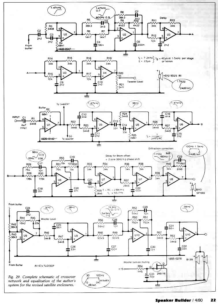
Thanks Charlie, and in addition here is excerpt of Mr.Sigfried implementation of this filter (in the midrange filter fifth block, and tweeter second block)
I will definitely use this high-pass filter in my design, and encourage anyone who wants to use a subsonic filter to use this implementation, the benefits are seen from the pictures in my previous posts. Lowest phase deviation, very low delay and almost equal frequency and Xmax characteristics with L-R 24dB/oct.
I will definitely use this high-pass filter in my design, and encourage anyone who wants to use a subsonic filter to use this implementation, the benefits are seen from the pictures in my previous posts. Lowest phase deviation, very low delay and almost equal frequency and Xmax characteristics with L-R 24dB/oct.
Excelent, I was just working out the details for my 3 X 8" sub boxes and I needed a subsonic filter as the excursion will go through the roof below 25hz!
I will give this a try.")
In Winlsd I have found that Linkwitz Transform has a lesser degree of group delay than does the Parametric eq.
I was not aware that it could be used in reverse!
jer
I will give this a try.
In Winlsd I have found that Linkwitz Transform has a lesser degree of group delay than does the Parametric eq.
I was not aware that it could be used in reverse!
jer
If you have say a mid in a sealed box with say q=0.5 Fs 90Hz, you can use LT to change to say Q=0.707 Fs 300Hz, thus the mid is now filtered with a classic butterworth rolloff at -3dB at 300Hz (true acoustical output). Add a separate 12dB butterworth stage (after LT) at 300Hz and you end up with an true acoustical output of LR24 at 300Hz -6dB.
You can use this method on the tweeter filtering as well.
Thats how my 3 way active xover is.
I recommended you actually measure the box q/Fs to get accurate acoustical results.
nice!
- Status
- This old topic is closed. If you want to reopen this topic, contact a moderator using the "Report Post" button.
- Home
- Source & Line
- Analog Line Level
- "Reverse" Linkwitz Transform