Hello all,
I thought I would post about a modification I did to add a subwoofer crossover to an integrated amp. It came out pretty well, I think.
What I have is a NAD C315BEE integrated amp. This is their entry model from a couple of years ago and it has no separate pre-amp out or subwoofer out. Speakers are B&W 685s with an ASW610 subwoofer. I was using the subwoofer's
speaker-level inputs and it sounded OK.
But I got to thinking that the low frequencies were also going to the main speakers and even though they can't
reproduce, say, 30Hz they still get the signal. So I thought about "bi-amping" with the active subwoofer amp and the NAD and with an active crossover. I got a hold of the service manual for the NAD and found that there are actually jumpers on the circuit board between the pre-amp and power sections, all I needed to do was build in some connectors for a pre-amp
out/in.
First, I went ahead and built the crossover. It is a standard Linkwitz-Riley 24dB/octave circuit set for crossover at 59Hz. (I just added 10Hz to the -3dB frequency for the 685 speakers.) Graphing the response showed all was in order, no phase problems and crossover frequency just where I'd calculated. Cool!
Now it was time to open up the NAD and see about removing the jumpers and adding the connectors. Turned out that it was really easy to work on. They even have a panel on the bottom that, when removed, allows access to the underside of the circuit board. Anyway, once I got the covers off it looked like there would be room to actually mount the crossover inside. I knew from the schematic that there was +/-17V in there which could power the crossover (it only draws like 30mA so I wasn't worried about that).
So, this weekend I wired it all up and was truly surprised at how much more clear the lower notes sound. Whether rock, jazz, or concert orchestra, the low-end sound is just more transparent and real sounding.
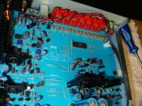
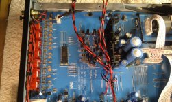
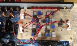
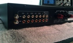
I attached a few pictures. The first shows the added subwoofer-out jacks (upper-right) with the location of the two removed jumpers (lower-middle, just to the left of a tall heatsink). The two jumpers just below the lower removed jumper are +/-17V. I removed them and replaced them with new jumpers with a little loop to solder to. I also drilled 5 small holes in the audio ground plane for the ground wires. The second picture shows the wiring in place. The third shows the crossover in place.
I thought I would post about a modification I did to add a subwoofer crossover to an integrated amp. It came out pretty well, I think.
What I have is a NAD C315BEE integrated amp. This is their entry model from a couple of years ago and it has no separate pre-amp out or subwoofer out. Speakers are B&W 685s with an ASW610 subwoofer. I was using the subwoofer's
speaker-level inputs and it sounded OK.
But I got to thinking that the low frequencies were also going to the main speakers and even though they can't
reproduce, say, 30Hz they still get the signal. So I thought about "bi-amping" with the active subwoofer amp and the NAD and with an active crossover. I got a hold of the service manual for the NAD and found that there are actually jumpers on the circuit board between the pre-amp and power sections, all I needed to do was build in some connectors for a pre-amp
out/in.
First, I went ahead and built the crossover. It is a standard Linkwitz-Riley 24dB/octave circuit set for crossover at 59Hz. (I just added 10Hz to the -3dB frequency for the 685 speakers.) Graphing the response showed all was in order, no phase problems and crossover frequency just where I'd calculated. Cool!
Now it was time to open up the NAD and see about removing the jumpers and adding the connectors. Turned out that it was really easy to work on. They even have a panel on the bottom that, when removed, allows access to the underside of the circuit board. Anyway, once I got the covers off it looked like there would be room to actually mount the crossover inside. I knew from the schematic that there was +/-17V in there which could power the crossover (it only draws like 30mA so I wasn't worried about that).
So, this weekend I wired it all up and was truly surprised at how much more clear the lower notes sound. Whether rock, jazz, or concert orchestra, the low-end sound is just more transparent and real sounding.
I attached a few pictures. The first shows the added subwoofer-out jacks (upper-right) with the location of the two removed jumpers (lower-middle, just to the left of a tall heatsink). The two jumpers just below the lower removed jumper are +/-17V. I removed them and replaced them with new jumpers with a little loop to solder to. I also drilled 5 small holes in the audio ground plane for the ground wires. The second picture shows the wiring in place. The third shows the crossover in place.
Attachments
Last edited:
Thanks Forsman
Yes, all of the resistors are Vishay Cermet trimmers. (The 2R positions are metal film in series with a trimmer.) The reason was to be able to adjust the crossover point as you suggest. The board was the prototype but it works and I saw no reason to build it again.
FYI, the capacitors are 0.1microFarad (1%) and the R values are 19K06. That gives 59Hz with Linkwitz' formula 1/(2.83*PI*R*C). The op-amps are all TI OPA2134.
I know that this all results in a pretty dedicated setup, but it would be relatively easy to put things back to where they were or change the crossover point for a different speaker. That's in the spirit of DIY anyway, right?
Last edited:
Hi hummel
If it is possible it would be interesting to see a picture of the flipside of the filter.
Do you have a schematic to show it would also be of interest?
I am a bit ambivalent whether I should try to build a similar filter or by a simple Behringer. I have heard some negative critique of the Behringer and it would be grate fun to do it my selves. And you seem to have solved the concern I had with building a filter of my own, namely the changeable crossover point.
Kind regards
/Fredrik
Hallo Fredrik,
I'm at work right now but I can get the board layout to you this evening. I do not know about Behringer products but an active filter is really pretty simple to build. Even I could do it!
The circuit I used is the standard Linkwitz-Riley 24dB/octave filter described at Mr. Linkwitz' web page (Active Filters). The same circuit is also described on the Elliott Sound Products site (Linkwitz-Riley Electronic Crossover). Figure 1A shows the full circuit for one channel. The 2C on the schematics is just two capacitors in parallel and 2R is two resistors in series. The only real problem with this topology is that the component value tolerances should be pretty tight to reduce phase problems. The ESP site explains that pretty well.
One big advantage of this kind of filter is that the outputs (LP and HP) are in phase. (Well, actually 360deg. out of phase but that's as good as zero.) A really cool test is to mix the two outputs and watch the combined output on the 'scope while feeding a sweep frequency. The combined output of the crossover I built stays absolutely the same from 10Hz, through the crossover frequency and on to 1000Hz. Cool.
I'll post or PM this evening with my layout.
- Michael
- Status
- This old topic is closed. If you want to reopen this topic, contact a moderator using the "Report Post" button.