Hi, im new to these forums and i need some help. Im a newbie so please bear with me. I have a stav-3470 receiver and it does not have preamp outs for the L and R channels. I am currently pushing the receiver pretty hard and occasionally the screen dims and it distorts/clips slightly when the bass hits so i need preamp outs to be able add external amps to take some of the load off my receiver. If i tooks some pics of the inside could a kind member tell me where i could find a line level signal that i could use to run to some external rca jacks? I assume i could find one near the circuit board that does the volume control. I would like to do all this for free with parts i currently have and as simple as possible. . thanks for any help.
Options...
If it uses a "normal" volume control (a pot rather than electronic attenuator) then taking the signal from the wiper of the pot and ground will give a feed that alters with the receivers volume setting.
Take the feed from the "top" of the pot and the level would be fixed.
The first option runs the real risk of an external amp "loading" or pulling down the level making the control range of the main volume control seem a bit odd. If the external amp presented much capacitance as a load then the hf response could be affected. A simple FET buffer or FET opamp would eliminate both these issues entirely though.
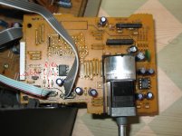
Hi, thanks for the reply. Yes the reciever uses a pot but im pretty sure that it also has op amps on the volume circuit board. I found 4 wires that went from the volume control to the amps labeled L and LG and R and RG. Is that were i would find my signal? I checked with a multimeter and the two Gs are connected to the chassis of the receiver. Check out the pic i took and tell me if thats the best source for a preamp signal.
Attachments
Hi ivoh,
It's not really possible to tell from that pic alone... one of the underside might help.
Most pots have 3 pins (6 for stereo pot) with the wiper being the center one. If yours has 4 (8 for stereo excluding the motor of course) then it sounds like it has a "tapping" for a loudness feature.
If you haven't got a scope what you can try is this. First make sure that with the unit on that there is zero volts on both pins 1 and 7 of those opamps.
If so carefully connect one side of a pair of headphones via a resistor of say 470 ohms to pin 1 of each IC and see if the audio varies with the volume control. But be careful ! as any slip could be very loud in the phones.
My pot has alot more than just 8 as the receiver is a pro-logic one. but most of the pins on the pot are labeled as to which channel they control. Both of the op amps ( the things with 4 pins on each side right?) have 0v at pins 1 and 7. I think the one i should be looking at is the one in the section labeled L/R buffer as its for the l and r channels right? There should be audio on pin one (i set my multimeter on ac and mesured) and it is affected by the volume level but it is <.100v even when turned up petty loud ( about halfway up) are these levels normal? I took a picture of the underside but for some reason i could not upload it sorry. Thanks for the help.
Last edited:
Maybe the pic was to big a file size.
Measuring audio on a meter isn't representative or accurate. It shows something is there but that is all. Audio is full of peaks and the meter has a very slow response so they just don't register. So yes it's normal.
The one you mention (L/R buffer) certainly sounds like the correct one.
When you get it all working those 4558 opamps could very usefully be upgraded... the 4558 is little better than a 741 in many ways. Something like the TL072 would be a direct swap and shouldn't cause any problems at all.
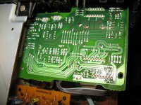
Yay i resized it and it worked lol. So do i just run pins 1 and 7 to my l and r rca jacks or will i need to add capacitors or resistors or somethin? Also pins 1 and 7 go to some capacitors so do i connect before or after the caps? Take a look at the pic if that tells you anything. About upgrading the opamp i think that would probably end in me destroying the circuit board somehow so i think i should pass on doing that for now.
Attachments
Last edited:
Thanks for the pic, that volume control looks a bit unique.
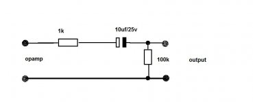
Assuming that opamp is the main L and R as you want (I can't tell for 100% sure just from pic but it looks as though it is) then it would be a good idea to isolate the output with a cap/resistor like this.
As for swapping opamps... get an old pcb of anything and practice desoldering using braid and a good hot iron. They would come out in seconds")
Assuming that opamp is the main L and R as you want (I can't tell for 100% sure just from pic but it looks as though it is) then it would be a good idea to isolate the output with a cap/resistor like this.
As for swapping opamps... get an old pcb of anything and practice desoldering using braid and a good hot iron. They would come out in seconds
Attachments
- Status
- This old topic is closed. If you want to reopen this topic, contact a moderator using the "Report Post" button.
- Home
- Source & Line
- Analog Line Level
- Help a Newb add preamps to his receiver.