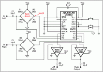
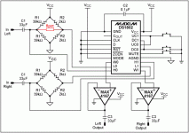
Hello everyone. I've been trying to build a simple volume control circuit using the DS1802. I have built a circuit almost identical to the circuit mentioned in Maxim's appnote. The only difference is the opamp. I've used a NE5532 in unity-gain configuration instead of the MAX4167. I'm powering the circuit with a 5 V supply and as a signal source I've been using a line level source, but also tried to further attenuate the source with a voltage divider. In either case the circuit basically works (without any clipping), but the attenuation of the DS1802 is very unsatisfying. While the upper 32 steps or so work as I would expect it, the rest barely makes any difference and even with mute enabled (which is said to attenuate by at least 90 db) I still can clearly hear the audio. Does anyone have an idea what I might have done wrongly or how to improve the circuit to get a better attenuation?
Thanks for the reply. According to the datasheet the NE5532 should work with +/-3 V, which is basically the same as single supply +6 V. You are right though, that 5 V is below the rated minimum of 6 V, but it seems that this is not the problem here. I have noticed that the maximum attenuation improves when I reduce the values of the R2 resistors. Using 1 Kohms for each of the resistors (instead of 2 Kohms) reduces the volume at the lowest value considerably. Using 470 ohms reduces it even more. Of course this increases the current flowing through the resistors. :/
If you want to operate the NE5532 with single power supply then you must make some changes to the circuit in the appnote.You need to make the virtual earth, wich will be at the middle of your supply voltage of +6 V.In your case it will be at +3V and then you need to block the DC at output.
Look here: Basic Op Amp Design
Look here: Basic Op Amp Design
As I said, it is exactly the circuit from the applicagtion note, except for the opamp, where I have used a NE5532 instead of the Maxim opamp.
An externally hosted image should be here but it was not working when we last tested it.
If you want to operate the NE5532 with single power supply then you must make some changes to the circuit in the appnote.You need to make the virtual earth, wich will be at the middle of your supply voltage of +6 V.In your case it will be at +3V and then you need to block the DC at output.
Look here: Basic Op Amp Design
There is a virtual ground in that circuit already. That's what the wheatstone bridge is for. The signal is aligned at VCC/2 through the whole signal path.
I don't know why it does not work.It's hard to say because I don't know how this DS1802 works inside.You can experiment with it.Try without the opamps or another type.
I would measure the voltage on output of the opamp and if it's 3V DC then they are working and the problem is somewere else.
I would measure the voltage on output of the opamp and if it's 3V DC then they are working and the problem is somewere else.
Last edited:
There was no distortion, at least none that was audible and I am pretty sure I would have noticed distortion caused by clipping. Why would that be impossible with 5 V? The opamps are configured to run with unity-gain, so there is no voltage amplification. Also, with the MP3 player I have tried with various output levels. It makes no difference at all (except for the absolute volume which is of course lower if I reduce the mp3 player's output level).
I just completed the prototype for a basic cmoy type amp with the DS1802. I used this circuit for the ds1802. Though with this a 2V source would be too high.
http://circuit-zone.com/ediy_blog/70/ds1802_sch.gif
I tried the bridge approach like in the app notes but I had some noise problems and some other problems. I cant remember if I had other issues because this little chip gave me alot of problems initially.
No audible noise or zipper noise using push buttons (Im about to start coding a uC for IR control)
Just thought I might pop in if you are still having problems.
solution (probably)
some0ne: this may be a tad too late, but i've faced the same problem recently and i think i finally managed to crack it:
the circuit is similar to this one: http://www.maxim-ic.com/images/appnotes/161/161Fig05.gif except the buffer is made with a different ic (lm4562 powered from +/-9V in my case). the problem appears to be the wheatstone bridge. the high side of the pot is connected to the R1s' common and the lower side to the R2s' common. so, there is actually a 50k resistor pulling the lower side of the pot as the high side swings due to input signal (Rpot in the attached picture). consequently, when the pot is set to its lowest position a lot of the signal bleeds through Rpot and passes to the buffers.

This could be mitigated by reducing the R2 values, bridging the R2s with large (and low ESR) capacitors or by creating a tough virtual ground.
For me a 33uF low-esr cap placed across the lower R2s and reducing them to 1k solved that problem (mute function really mutes). I am still going to try replacing the upper R2s with a constant current source
some0ne: this may be a tad too late, but i've faced the same problem recently and i think i finally managed to crack it:
the circuit is similar to this one: http://www.maxim-ic.com/images/appnotes/161/161Fig05.gif except the buffer is made with a different ic (lm4562 powered from +/-9V in my case). the problem appears to be the wheatstone bridge. the high side of the pot is connected to the R1s' common and the lower side to the R2s' common. so, there is actually a 50k resistor pulling the lower side of the pot as the high side swings due to input signal (Rpot in the attached picture). consequently, when the pot is set to its lowest position a lot of the signal bleeds through Rpot and passes to the buffers.

This could be mitigated by reducing the R2 values, bridging the R2s with large (and low ESR) capacitors or by creating a tough virtual ground.
For me a 33uF low-esr cap placed across the lower R2s and reducing them to 1k solved that problem (mute function really mutes). I am still going to try replacing the upper R2s with a constant current source
Attachments
- Status
- This old topic is closed. If you want to reopen this topic, contact a moderator using the "Report Post" button.
- Home
- Source & Line
- Analog Line Level
- Problem with DS1802 digital volume control IC
